
Petroleum drilling real-time monitoring system

A real-time monitoring system and oil drilling technology, which is applied in the directions of measurement, earthwork drilling, wellbore/well components, etc., can solve the problem that the oil drilling system cannot realize real-time monitoring, the drilling fluid cannot realize real-time monitoring, and the medium pressure loss of water detection index Inaccurate and other problems to achieve the effect of avoiding drilling accidents, reasonable structure and accurate monitoring data

Inactive Publication Date: 2015-06-10
韩文峰
View PDF4 Cites 2 Cited by
  • Summary
  • Abstract
  • Description
  • Claims
  • Application Information

AI Technical Summary

Problems solved by technology

The disadvantage of this method is that the temperature of the drilling fluid changes greatly when it is taken back from the operation site to the laboratory, and the viscosity of the drilling fluid changes accordingly. The detected data is not the viscosity data during drilling, and Generally, it is only monitored once every 8-12 hours, and the judgment of performance changes and other threats to drilling safety accidents cannot be timely and accurate; in addition, due to large changes in the temperature of the drilling fluid, other performance changes can also be caused, resulting in medium pressure The detection index of water loss is inaccurate; at the same time, the sand content and solid phase content in the drilling fluid change greatly in a certain period of time
Since the drilling fluid cannot be monitored in real time, the oil drilling system cannot be monitored in real time

Method used

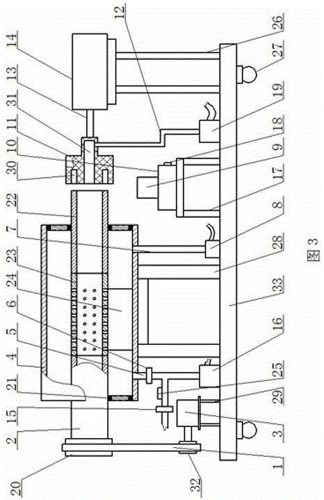

Image

  • Petroleum drilling real-time monitoring system
  • Petroleum drilling real-time monitoring system
  • Petroleum drilling real-time monitoring system

Examples


Embodiment Construction

[0011] The oil drilling real-time monitoring system of the present invention includes a drilling fluid performance monitoring instrument, a geological logging monitoring instrument and a drilling engineering parameter monitoring instrument. Sensors are installed on each instrument, and the sensor transmits the detection signal to the computer through a wireless transmitting and receiving system Processing equipment, and then processed by computer software, converted into charts and displayed on the monitor in real time. Wherein the geological logging monitoring instrument and the drilling engineering parameter monitoring instrument are prior art, for these prior art, the present embodiment only describes the name of each part and related parameters used in the oil drilling real-time monitoring system: geological logging real-time monitoring part , consisting of spectrometer, fluorescence content measuring instrument, hydrogen flame chromatograph, thermal conductivity chromatogr...


PUM


Abstract

The invention provides a petroleum drilling real-time monitoring system which comprises a drilling liquid performance monitoring instrument, a geological logging monitoring instrument and a drilling engineering parameter monitoring instrument, wherein sensors are arranged on all the instruments; the sensors are used for transmitting a detecting signal to computer processing equipment through a wireless transmitting and receiving system, and the detecting signal is processed through the computer software and then converted into a chart to be displayed through a display in real time. With the adoption of the petroleum drilling real-time monitoring system, the shortcomings of the comprehensive logging instrument that only the geological logging and drilling engineering parameters can be monitored can be overcome; the drilling liquid performance can be monitored online in real time, so that the drilling liquid, the drilling engineering and the geological logging can be integrated and processed through a computer, and then a comprehensive system integrating the acquiring, displaying and processing of various data at a drilling site can be formed; the comprehensive system can meets the various demands of safely optimizing the drilling and comprehensively determining an oil-gas-water layer.

Description

technical field [0001] The invention relates to oil drilling monitoring technology, which is a real-time monitoring system for oil drilling. Background technique [0002] Drilling real-time monitoring technology is a professional technology integrating drilling fluid, drilling engineering and geological logging. Therefore, in drilling construction, the application of drilling real-time monitoring system is very necessary. [0003] Currently, a comprehensive mud logging instrument is used to monitor oil drilling conditions. However, this instrument can only monitor geological logging and drilling engineering parameters, and cannot monitor drilling fluid in real time. Therefore, real-time monitoring of oil drilling cannot be realized. Drilling fluid needs to be monitored during oil drilling to prevent accidents that threaten safe drilling such as changes in drilling fluid performance during drilling. The monitoring indicators of drilling fluid are generally divided into: visc...

Claims


Application Information

Patent Timeline
Patent Type & Authority Patents(China)
IPC IPC(8): E21B49/08E21B47/12
Inventor 韩晓玲杨超韩文峰
Owner 韩文峰
Learn More