Double-throttle control slurry pump distributing manifold for applying wellhead back pressure and method

A mud pump and shunt pipe technology, which is applied in the field of double throttle control mud pump shunt manifold, can solve the problems of back pressure pump leakage pollution, non-production time increase, bottom hole pressure control inaccuracy, etc.

Active Publication Date: 2012-12-19
CHINA UNIV OF PETROLEUM (EAST CHINA) +1
View PDF4 Cites 21 Cited by
  • Summary
  • Abstract
  • Description
  • Claims
  • Application Information

AI Technical Summary

Problems solved by technology

Managed pressure drilling requires that the drilling pump be started and stopped step by step according to the specified pump strokes during the process of starting and stopping the pump, so as to realize the stepwise increase and decrease of the drilling fluid in the wellbore according to the regulations, but the electric drilling rig, especially the mechanical drilling rig The pump and stop of the pump cannot be precisely controlled, resulting in generally poor continuity and stability of bottomhole pressure control and inaccurate bottomhole pressure control
[0006] The limitations of using back pressure pumps to apply wellhead back pressure also include: adding additional back pressure pumps to the drilling system not only increases costs (including maintenance costs), but also requires more space; due to back pressure pump failure, loading and unloading and complex The additional operation brought about by the increase of sexual property will increase the non-production time and increase the cost of drilling; the leakage of the back pressure pump may cause pollution

Method used


Image

  • Double-throttle control slurry pump distributing manifold for applying wellhead back pressure and method
  • Double-throttle control slurry pump distributing manifold for applying wellhead back pressure and method
  • Double-throttle control slurry pump distributing manifold for applying wellhead back pressure and method

Examples


Embodiment Construction

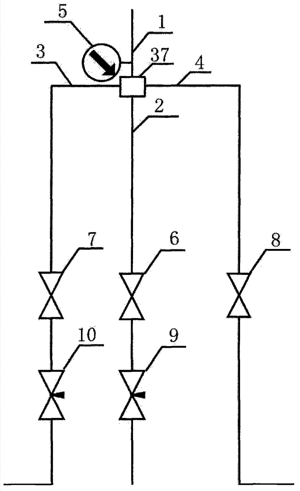
[0081] Such as figure 1 As shown, the diversion manifold of the mud pump with double throttling control includes the main pipe 1, the manifold cross 37, the first diversion line 2, the second diversion line 3 and the third diversion line 4; the manifold cross 37 is respectively connected to the main pipe 1 , the first shunt line 2, the second shunt line 3 and the third shunt line 4; the main pipe 1 is equipped with a pressure gauge 5; the first shunt line 2 is equipped with a first cut-off valve 6 and a first throttle valve 9, the first A shut-off valve 6 is located between the first throttling valve 9 and the manifold spool 37; a second shut-off valve 7 and a second throttling valve 10 are installed on the second branch line 3, and the second shut-off valve 7 is located in the second joint Between the flow valve 10 and the manifold spool 37; the third cut-off valve 8 is installed on the third diversion line 4. The diversion of the drilling fluid is realized by switching the ...


PUM


Abstract

The invention belongs to the technical field of oil drilling, and relates to a double-throttle control slurry pump distributing manifold for applying wellhead back pressure and a method. The double-throttle control slurry pump distributing manifold for applying the wellhead back pressure comprises a main pipe, a manifold four-way joint, a first distributing pipeline, a second distributing pipeline and a third distributing pipeline; the manifold four-way joint is respectively connected with the main pipe, the first distributing pipeline, the second distributing pipeline and the third distributing pipeline; a pressure gauge is installed on the main pipe; and the first distributing pipeline is provided with a first stop valve and a first throttling valve, the second distributing pipeline is provided with a second stop valve and a second throttling valve, and the third distributing pipe is provided with a third stop valve. The pump is unnecessary to stop and start in the connecting process, the pulling out process and the drilling down process, so that the pressure fluctuation on the bottom of a well can be reduced, and the control capacity for the bottom pressure can be improved; a back pressure pump is not needed, so that additional work caused by the back pressure pump is avoided, the nonproduction time can be reduced, and the drilling cost can be reduced; the pollution caused by the leakage of the back pressure pump can be avoided; and the energy and the floor area can be saved.

Description

technical field [0001] The invention belongs to the technical field of petroleum drilling, and relates to a pressure-controlled drilling method, in particular to a double-throttle control mud pump shunt manifold and method for applying wellhead back pressure. Background technique [0002] At present, with the continuous expansion of deepwater oil and gas exploration and development scale and the increasing number of onshore exploration and development activities in more complex formations, the deep water environment and geological conditions of deep formations are becoming more and more complex. The window between formation fracture pressure and pore pressure is often narrow. During the drilling process, downhole complex situations such as blowout, leakage, sticking, and collapse often occur, and even leakage and blowout coexist. This not only prolongs the drilling cycle, but also increases the drilling cost. And it has brought serious safety and environmental protection pro...

Claims


Application Information

Patent Timeline
IPC IPC(8): E21B21/12E21B21/10E21B21/08
Inventor 孙宝江王志远孙文超周翔高永海李昊
Owner CHINA UNIV OF PETROLEUM (EAST CHINA)
Why Eureka
Try Eureka