
Rapid locking mechanism for stirring paddle

A technology of locking mechanism and stirring paddle, which is applied in the direction of mixer accessories, mixers, dissolving, etc., can solve the problems of inability to achieve fast locking installation and disassembly, inconvenient quick disassembly, etc., and achieve reduced machine downtime, convenient processing, and high performance reliable effect

Active Publication Date: 2014-06-25
LIUZHOU HUT CHEM MACHINERY
View PDF4 Cites 0 Cited by
  • Summary
  • Abstract
  • Description
  • Claims
  • Application Information

AI Technical Summary

Problems solved by technology

[0005] The above connection methods need to be fastened with bolts or pins. The first connection method relies on the friction force formed by bolt locking to transmit torque, and the second connection method uses pins to transmit torque, but the above two connection methods are not convenient. For quick disassembly, it is necessary to loosen the bolts or remove the pins to separate the stirring paddle and the stirring shaft, which cannot achieve the purpose of fast locking installation and disassembly

Method used


Image

  • Rapid locking mechanism for stirring paddle
  • Rapid locking mechanism for stirring paddle
  • Rapid locking mechanism for stirring paddle

Examples


Embodiment 1

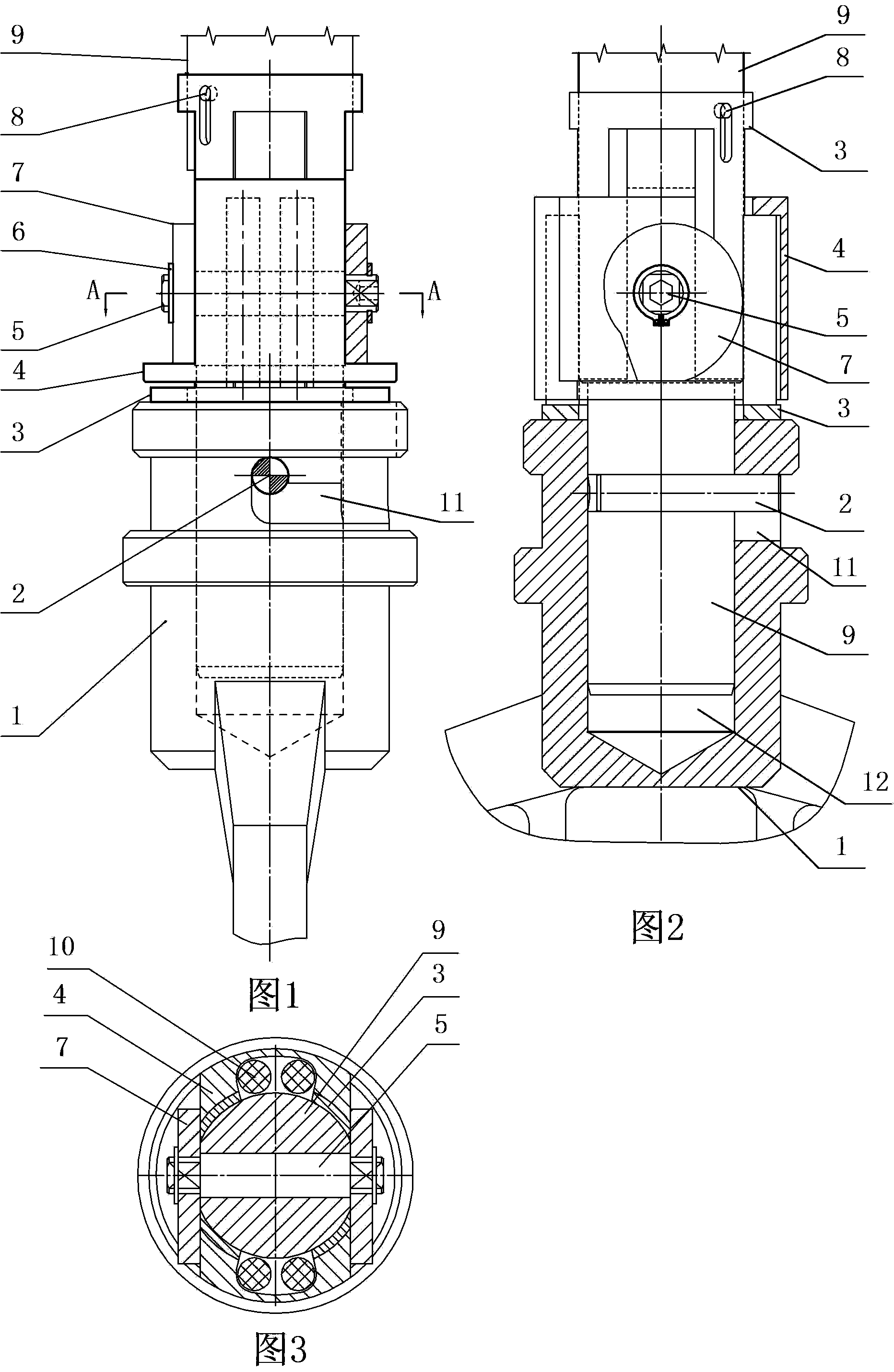
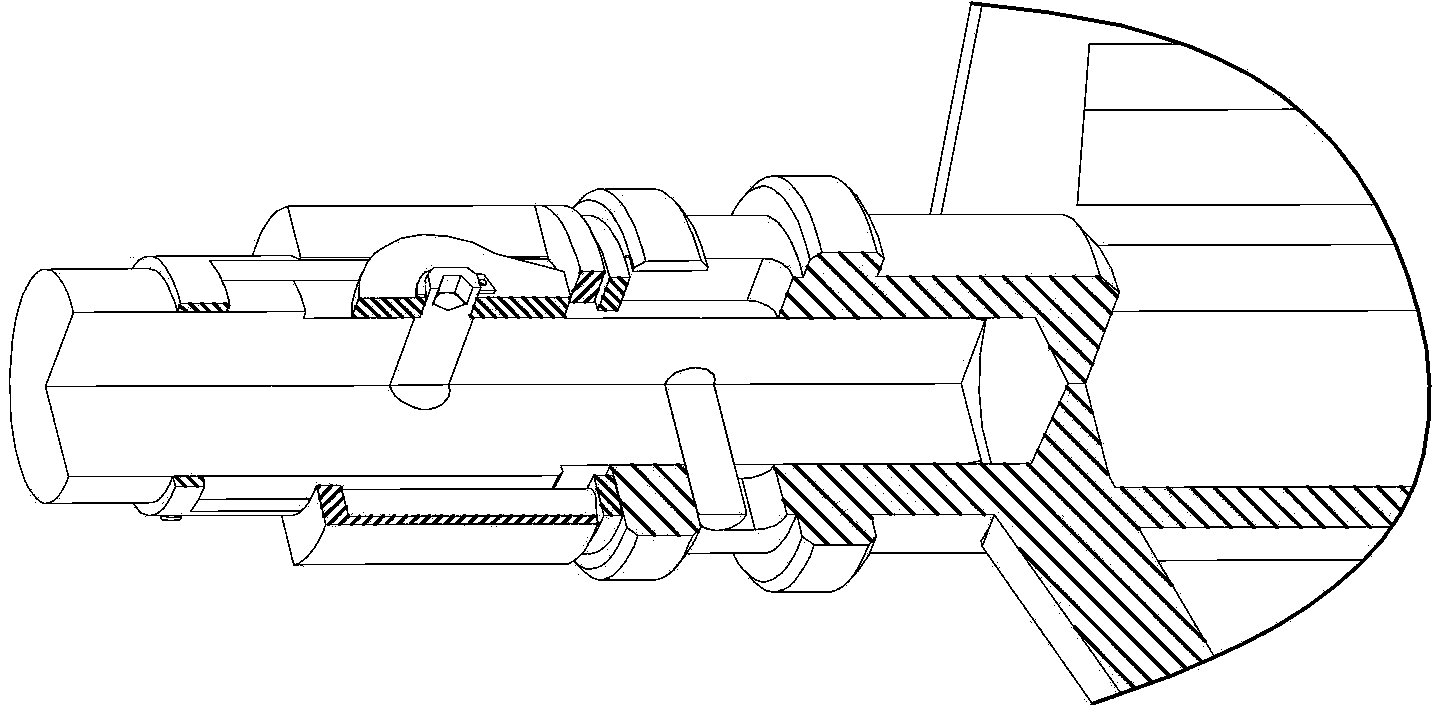
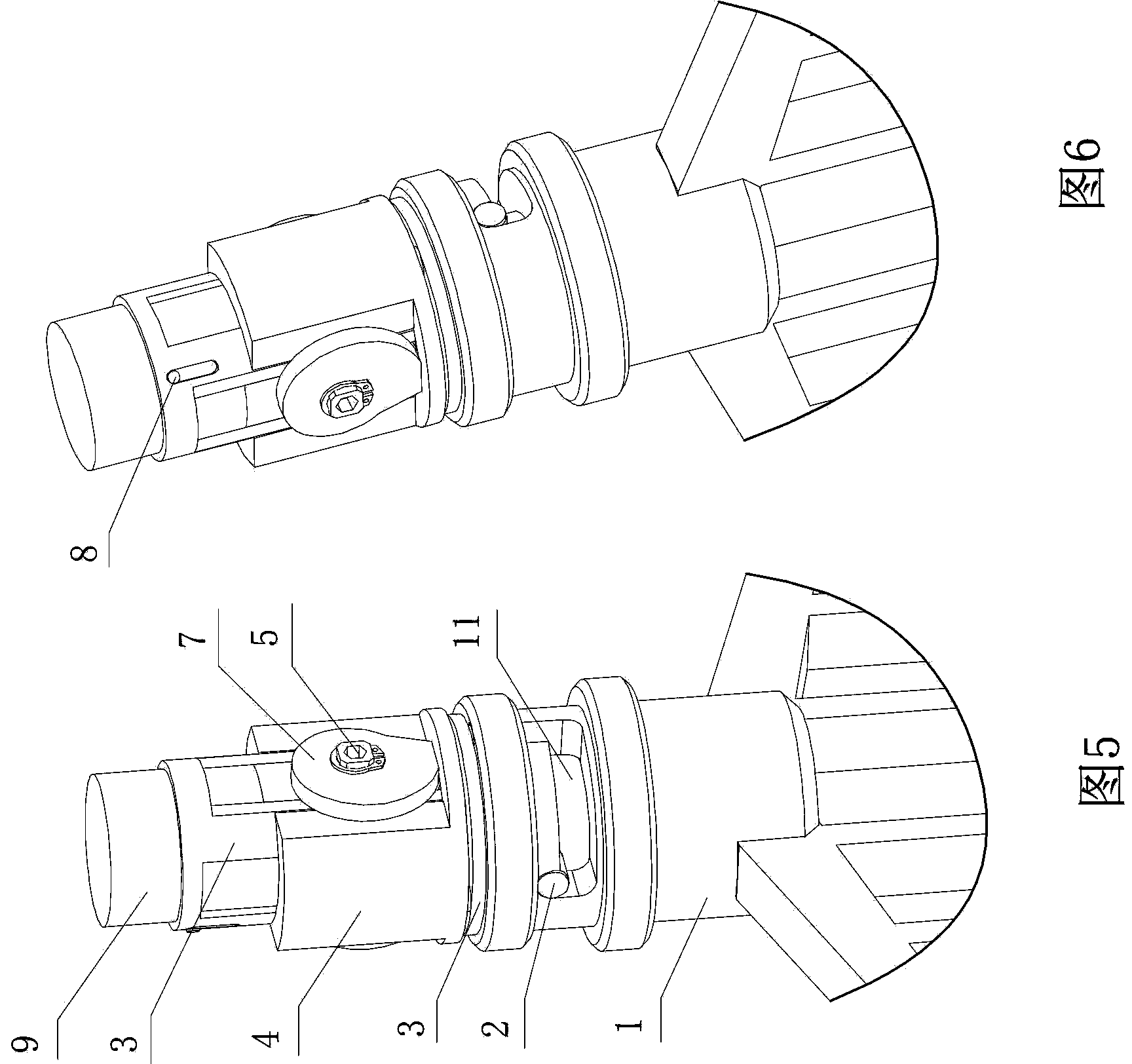
[0035] Embodiment 1: A quick locking mechanism for stirring paddles, such as Figure 1 to Figure 6 As shown, it includes a stirring shaft 9, a stirring paddle 1 with a stirring shaft installation groove 12 on the top, a pressure sleeve 3, a rubber strip holding sleeve 4, a rubber strip 10 and two cams 7, and the stirring shaft 9 is provided with a drive Pin hole 93, driving pin 2 is fixedly installed in the driving pin hole, camshaft installation hole 92 is provided on the stirring shaft above the driving pin hole, and a mirror with the straight line of the vertical horizontal line as the axis is provided on the described stirring paddle 1. L-shaped groove 11, the groove is simple and suitable for processing, the stirring shaft 9 is installed in the stirring shaft installation groove 12 of the stirring paddle 1, and in the locked state, the driving pin 2 on the stirring shaft is located in the mirror direction L of the paddle In the position 111 at the end of the type groove (...


PUM


Abstract

The invention relates to a rapid locking mechanism for a stirring paddle. The rapid locking mechanism for the stirring paddle comprises a stirring shaft, the stirring paddle, a pressure sleeve, an adhesive tape retaining sleeve, adhesive tapes and two cams, wherein the stirring shaft is arranged in the stirring paddle; a drive pin arranged on the stirring shaft is located in a groove arranged on the stirring paddle; the pressure sleeve is sheathed onto the stirring shaft; the adhesive tape retaining sleeve is sheathed onto the pressure sleeve; the adhesive tapes are arranged between the pressure sleeve and the adhesive tape retaining sleeve; the upper ends and the lower ends of the adhesive tapes are respectively contacted with the top end of the adhesive tape retaining sleeve and the bottom end of the pressure sleeve; the two cams are respectively arranged at both sides of the stirring shaft through a cam pin shaft; and when in a locking state, the bottom end of the adhesive tape retaining sleeve is compressed tightly by the surface at the maximum diameter position of each cam; the adhesive tape retaining sleeve and the pressure sleeve are respectively supported by the upper ends and the lower ends of the adhesive tapes; and the upper end face of the stirring paddle is compressed tightly by the bottom end face of the pressure sleeve. According to the rapid locking mechanism for the stirring paddle, any parts do not need to be disassembled or assembled during the process of installing and disassembling the stirring paddle and the stirring shaft, thus, the stirring paddle and the stirring shaft are rapidly connected and are effectively locked; the stirring paddle replacement time and the stop time of equipment are shortened; and the utilization ratio of a machine is greatly increased.

Description

technical field [0001] The invention relates to a fast locking mechanism for stirring paddles, in particular to a fast locking mechanism for connecting paddles and stirring shafts for stirring and mixing equipment in chemical industry, electronic slurry, lubricating grease, pharmaceuticals, food and other industries. Background technique [0002] At present, in the mixing and stirring equipment used in the chemical industry, electronic slurry and other industries, the stirring shaft is inserted into the stirring shaft installation groove on the top of the stirring paddle, and the connection and fixing of the stirring paddle and the stirring shaft are generally adopted in the following two ways: [0003] 1. Using couplings and bolts; [0004] 2. Pin connection. [0005] The above connection methods need to be fastened with bolts or pins. The first connection method relies on the friction force formed by bolt locking to transmit torque, and the second connection method use...

Claims


Application Information

Patent Timeline
Patent Type & Authority Patents(China)
IPC IPC(8): B01F15/00
Inventor 梁健韦建敏韩林覃恒
Owner LIUZHOU HUT CHEM MACHINERY
Learn More