Diffusion Tube For Sludge Fluidized Bed Incinerator And Diffusion Device
A fluidized bed and incinerator technology, which is applied to incinerators, fluidized bed combustion equipment, and fuel burned in a molten state, to achieve the effect of ensuring operation stability and high natural vibration frequency
- Summary
- Abstract
- Description
- Claims
- Application Information
AI Technical Summary
Problems solved by technology
Method used
Image

Examples
no. 1 approach )
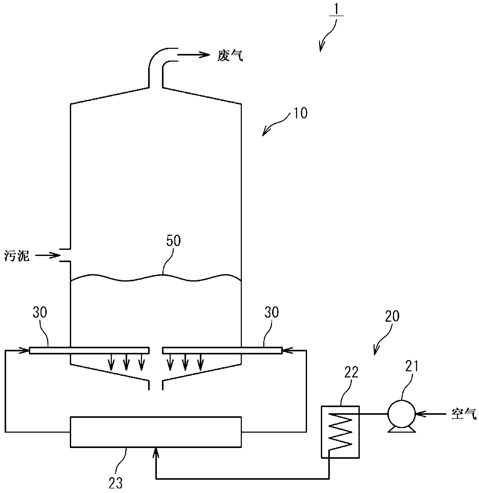
[0025] refer to figure 1 , The sludge treatment facility 1 according to the first embodiment of the present invention is provided with: a fluidized bed incinerator 10; The fluidized bed incinerator 10 incinerates sludge such as dirty water sludge, excrement treatment sludge, and various waste water treatment sludge. Hereinafter, the case where the fluidized bed incinerator 10 is a bubble type will be described, but the fluidized bed incinerator 10 may be a circulation type. The diffuser 20 includes an air supply device 21 such as a blower, an air preheater 22 , a header 23 , and a plurality of diffuser pipes 30 . The air supply device 21 is connected to a header 23 via an air preheater 22 . The header pipe 23 is connected to a plurality of diffuser pipes 30, respectively. Each air-diffusing pipe 30 is formed in a straight pipe shape, inserted into the fluidized-bed incinerator 10 so that the axis of the air-diffusing pipe 30 becomes horizontal, and supported by the fluidize...
no. 2 approach )
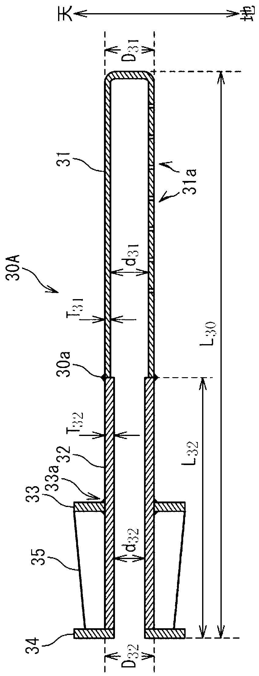
[0038] refer to Figure 4 , the diffuser tube 30A of the second embodiment of the present invention will be described. 30 A of diffuser tubes of this embodiment are comprised similarly to 30 A of diffuser tubes of 1st Embodiment except the following points. In this embodiment, the outer diameter D of the front end portion 31 31 than the outer diameter D of the root 32 32 Small and the inner diameter d of the front end portion 31 31 with the inner diameter d of the root 32 32 equal. In this embodiment, other diffuser tubes 30 including the diffuser tube 30B may be configured similarly to the diffuser tube 30A of the present embodiment, or may be configured similarly to the diffuser tube 30A of the first embodiment.
[0039] It should be noted that the outer diameter D of the front end portion 31 may also be 31 than the outer diameter D of the root 32 32 small and make the inner diameter d of the front end part 31 31 than the inner diameter d of the root 32 32 Big. In ...
no. 3 approach )
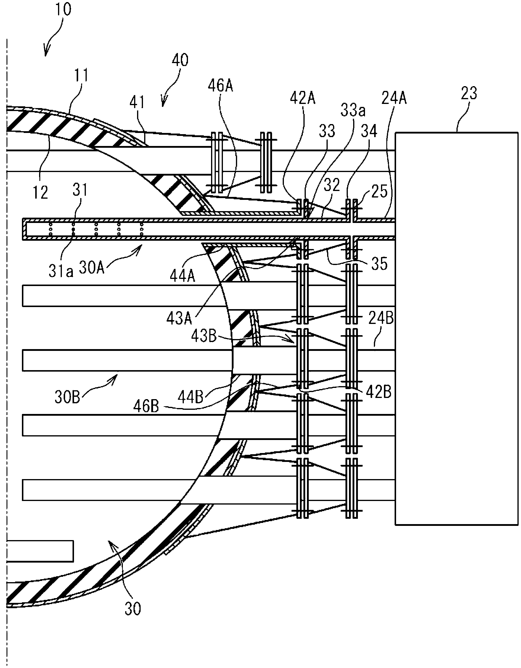
[0041] refer to Figure 5 , the support structure 40 of the third embodiment of the present invention will be described. The support structure 40 of this embodiment is the same as the support structure 40 of 1st Embodiment except the following point. The support structure 40 of the present embodiment includes a support plate 47 instead of the support plates 42A and 42B. The support structure 40 of this embodiment is equipped with the support rib 48 arrange|positioned between adjacent sleeves. Support ribs 48 are welded to adjacent sleeves, curved plate 41 , and support plate 47 .
[0042] Such as Figure 6 As shown, through-holes 47 a and 47 b are formed in the support plate 47 . Bolt holes (not shown) are formed around the respective through holes 47 a and 47 b.
[0043] The support plate 47 is welded to the sleeves 44A and 44B so that the through hole 47a communicates with the inside of the sleeve 44A and the through hole 47b communicates with the inside of the sleeve 4...
PUM
 Abstract
Description
Claims
Application Information
 - R&D
- Intellectual Property
- Life Sciences
- Materials
- Tech Scout
- Unparalleled Data Quality
- Higher Quality Content
- 60% Fewer Hallucinations
Browse by: Latest US Patents, China's latest patents, Technical Efficacy Thesaurus, Application Domain, Technology Topic, Popular Technical Reports.
© 2025 PatSnap. All rights reserved.Legal|Privacy policy|Modern Slavery Act Transparency Statement|Sitemap|About US| Contact US: help@patsnap.com