Circuit and method for balancing electric quantity of storage battery pack
A technology of battery pack and balancing circuit, applied in battery circuit devices, circuit devices, current collectors, etc.
- Summary
- Abstract
- Description
- Claims
- Application Information
AI Technical Summary
Problems solved by technology
Method used
Image
Examples
specific Embodiment approach 1
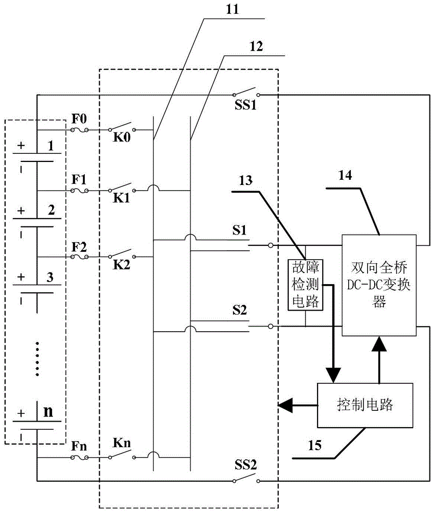
[0045] DETAILED DESCRIPTION OF THE PREFERRED EMBODIMENTS 1. A power balance circuit for battery packs, the battery pack is composed of N cells in series, where N is a positive integer greater than or equal to 2; it includes a switch network, a bidirectional full-bridge DC-DC converter 14, a fault Detection circuit 13 and control circuit 15;
[0046] Switching network: used to select any single battery in the battery pack, and make the single battery connect to the bidirectional full-bridge DC-DC converter 14 with the correct polarity;
[0047] Bidirectional full-bridge DC-DC converter 14: used to transfer the electric energy in the single battery with higher than standard electric power to the battery pack, or to transfer the electric energy of the battery pack to the single battery with lower than standard electric power;
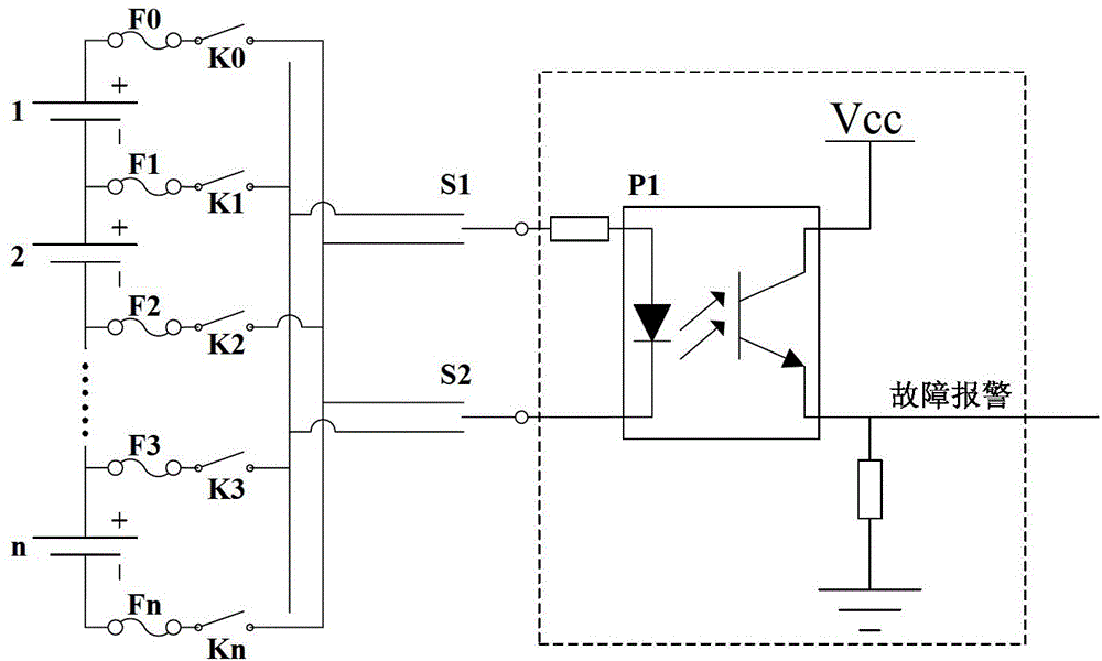
[0048] Fault detection circuit 13: used to provide protection in the event of a short circuit in the battery pack, and send out a fault alarm signal;
[...
specific Embodiment approach 2
[0050] Embodiment 2. The difference between this embodiment and the electric balance circuit for battery packs described in Embodiment 1 is that the switch network consists of N+1 No. 1 switch, No. 2 switch SS1, No. 3 switch SS2, a The No. 1 reversing switch S1, the No. 2 reversing switch S2, the even bus 11 and the odd bus 12; Odd-numbered bus 12; the positive and negative terminals of the single cells in even-numbered positions in the storage battery pack are respectively connected to the odd-numbered bus 12 and the even-numbered bus 11 through two No. 1 switches; the moving end of No. 2 switch SS1 and the moving end of No. 3 switch SS2 The terminals are respectively connected to the two ends of the battery pack; the static terminal of the second switch SS1 and the static terminal of the third switch SS2 are respectively connected to the two voltage signal terminals of the whole group side of the bidirectional full-bridge DC-DC converter 14; Both the No. 1 reversing switch S...
specific Embodiment approach 3
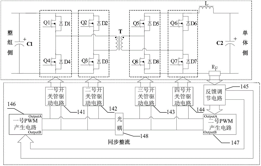
[0055] Embodiment 3. The difference between this embodiment and the electric balance circuit for battery packs described in Embodiment 2 is that the bidirectional full-bridge DC-DC converter 14 is composed of a main circuit and a converter control circuit;
[0056] The main circuit includes No. 1 switch tube Q1, No. 2 switch tube Q2, No. 3 switch tube Q3, No. 4 switch tube Q4, No. 5 switch tube Q5, No. 6 switch tube Q6, No. 7 switch tube Q7, and No. 8 switch tube Tube Q8, No. 1 diode D1, No. 2 diode D2, No. 3 diode D3, No. 4 diode D4, No. 5 diode D5, No. 6 diode D6, No. 7 diode D7, No. 8 diode D8, transformer T, inductor L, a No. filter capacitor C1, No. 2 filter capacitor C2 and current detection resistor R F ;
[0057] The first diode D1 is anti-associated with the first switch tube Q1; the second diode D2 is anti-correlated with the second switch tube Q2; the third diode D3 is anti-correlated with the third switch tube Q3; the fourth diode D4 is anti-correlated with the fo...
PUM
 Abstract
Description
Claims
Application Information
 - Generate Ideas
- Intellectual Property
- Life Sciences
- Materials
- Tech Scout
- Unparalleled Data Quality
- Higher Quality Content
- 60% Fewer Hallucinations
Browse by: Latest US Patents, China's latest patents, Technical Efficacy Thesaurus, Application Domain, Technology Topic, Popular Technical Reports.
© 2025 PatSnap. All rights reserved.Legal|Privacy policy|Modern Slavery Act Transparency Statement|Sitemap|About US| Contact US: help@patsnap.com


