A single power supply multi-electrode arc ignition device and method

An arc ignition and multi-electrode technology, applied in the field of single power supply multi-electrode arc ignition devices, can solve the problems of not being able to further increase the number of ignition electrodes, not conforming to the arc ignition cable, reducing the power output efficiency, etc., so as to improve the power output efficiency, Improve power efficiency, the same effect of power

Active Publication Date: 2021-09-07
STATE GRID JIANGSU ELECTRIC POWER CO ELECTRIC POWER RES INST
View PDF6 Cites 0 Cited by
  • Summary
  • Abstract
  • Description
  • Claims
  • Application Information

AI Technical Summary

Problems solved by technology

This method is affected by the structure of the center tap of the choke coil, and cannot further increase the number of ignition electrodes, and the scalability is poor
Moreover, the inductance elements connected in series in the circuit of this scheme increase the reactive part of the output power of the power supply and reduce the output efficiency of the power supply.
Moreover, although this solution can generate an arc, the arc is still generated and extinguished periodically, which cannot burn stably, and does not meet the needs of the arc ignition cable experiment.

Method used


Image

  • A single power supply multi-electrode arc ignition device and method
  • A single power supply multi-electrode arc ignition device and method
  • A single power supply multi-electrode arc ignition device and method

Examples


Embodiment 1

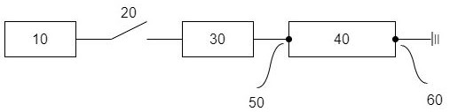
[0111] The single power supply multi-electrode arc ignition device in the preferred embodiment of the present invention is as Figure 4 As shown, it includes a DC voltage power supply 1, an air switch 2, an LC oscillating circuit 3, a high voltage pack 4, and a multi-electrode ignition group 5.

[0112] The DC voltage source 1 is electrically connected to the input terminal of the LC oscillator circuit 3 through the air switch 2, so that the DC voltage source 1 provides a constant input voltage and current for the LC oscillator circuit 3; the LC oscillator circuit 3 reverses the DC voltage and current input by the DC voltage source 1 It becomes 20kHz AC voltage and current, and outputs it to the low-voltage side of the high-voltage pack 4; the high-voltage pack 4 boosts the alternating voltage transmitted by the LC oscillation circuit 3, and the high-voltage side of the high-voltage pack 4 outputs the boosted alternating voltage To the multi-electrode ignition group 5; the pos...

Embodiment 2

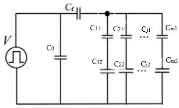
[0128] Such as Figure 8 , the multi-electrode ignition group includes four arc ignition branches, that is, the multi-electrode ignition group includes four sets of arc electrodes; the four arc ignition branches respectively include A claw electrode 6, B claw electrode 7, C claw electrode 10, D claw electrode 11, It also includes a first large inductance coil group 9 and a second large inductance coil group 12 , a first high voltage capacitor group 8 and a second high voltage capacitor group 13 .

[0129] Among them, the positive poles of the A horn electrode 6 , B horn electrode 7 , C horn electrode 10 , and D horn electrode 11 are connected to each other and electrically connected to one end of the high voltage side of the high voltage pack 4 .

[0130] Further, the negative pole of A claw electrode 6 is electrically connected with one end of the first high voltage capacitor group 8, the negative pole of B claw electrode 7 is electrically connected with one end of the first ...


PUM


Abstract

A single power supply multi-electrode arc ignition device and method, the ignition device includes a DC voltage source, an air switch, an LC oscillating circuit, a high voltage pack, and a multi-electrode ignition group; the multi-electrode ignition group includes 2n parallel connections between the positive access port and the negative The arc ignition branch between the access ports; each arc ignition branch includes a reactive device and a claw electrode; wherein, the positive pole of the claw electrode is connected to the positive pole access port of the multi-electrode ignition group, and the negative pole of the claw electrode is first connected in series The reactive device is then connected to the negative pole access port of the multi-electrode ignition group. The ignition device and method proposed by the present invention only use a single power supply to realize multi-electrodes to generate a continuous and stable arc that will not be extinguished periodically to meet the experimental requirements, and the power of each electrode is the same, and the power of the ignition device can be improved by extending the electrodes , so as to effectively solve the problem of lack of multi-electrode ignition devices required by the arc ignition method in the cable combustion test.

Description

technical field [0001] The present invention relates to the technical field of AC arc test devices, and more specifically, to a single-power multi-electrode arc ignition device and method. Background technique [0002] With the development of the power industry, cables play a vital role in every link of power generation, transmission, transformation, distribution, and power consumption, and are one of the important infrastructures for social production and people's lives. However, while the cable is exerting its normal working benefits, problems such as overload, short circuit, and leakage may occur due to line faults, and even fires may occur. In recent years, frequent large-scale power outages caused by cable fires have caused serious adverse social impacts. According to the statistics of my country's fire department, electrical fires have accounted for about 30% of all fires in my country in recent years; in the distribution of direct causes of electrical fires for major...

Claims


Application Information

Patent Timeline
Patent Type & Authority Patents(China)
IPC IPC(8): F23Q3/01
CPCF23Q3/01
Inventor 陈杰李陈莹胡丽斌谭笑曹京荥张伟黄强杨景刚刘建军袁栋李鸿泽刘利国
Owner STATE GRID JIANGSU ELECTRIC POWER CO ELECTRIC POWER RES INST
Why Eureka
Try Eureka