Synchronized multi-channel communication device and method

a multi-channel communication and synchronization technology, applied in the direction of synchronisation arrangement, transmission monitoring, wireless communication, etc., can solve the problems of transferring radio communication into difficult terrain or environments not well suited for v/uh

Active Publication Date: 2022-10-04
NOKOMIS
View PDF30 Cites 0 Cited by
  • Summary
  • Abstract
  • Description
  • Claims
  • Application Information

AI Technical Summary

Benefits of technology

[0008]The invention addresses how TeCI can be utilized to construct a transmitted signal that can be reconstructed across a long range, without Loss of Signal (LOS) and be reconstructed by a mobile receiving device. TeCI performed using precisely timed sample locations within a waveform enables the extraction of signals from transmissions that would be otherwise considered to be noise. By using time synchronized transmission and reception, fixed signal sampling over repeated waveforms can extract a frequency specific signal.
[0020]Intermittent transmissions may be used to lower the average power for a message of a specific length by encoding more virtual bits of information as time and or frequency slots while also obscuring the message. Alternatively, the intermittent transmission may serve to maintain the average power but increase the signal to noise ratio (SNR). The SNR increase is useful while receiving below, or near the noise floor. A precisely timed encoded message is transmitted in predetermined frequency or time slots, said slot locations being used to encode additional data content bits. Additionally, the transmission power of the message during the time slot may be higher or far higher than the average power, but the message may be transmitted far less often and / or of a briefer duration. Thus, the total power used for transmission may remain substantially the same, but more total message bit content may be sent. Additional open multiple time slots or frequency slots are also available for encoding or for other transmissions. An embodiment offers the use of: (1) greater transmission power during transmission periods accompanied by periods on non-transmission, while maintaining substantially the same average power overall, in combination with the and making available (2) time or (3) frequency slots. This allows for as many as 3 methods to beneficially combine to further increase SNR over using a precisely timed encoded message only sent continuously.

Problems solved by technology

The technical problem is to transmit a radio communication into an environment with difficult terrain or environments not well suited for V / UHF tactical communications without hardware relays.

Method used


Image

  • Synchronized multi-channel communication device and method
  • Synchronized multi-channel communication device and method
  • Synchronized multi-channel communication device and method

Examples


Embodiment Construction

Determining Optimal Coherent Integration Period

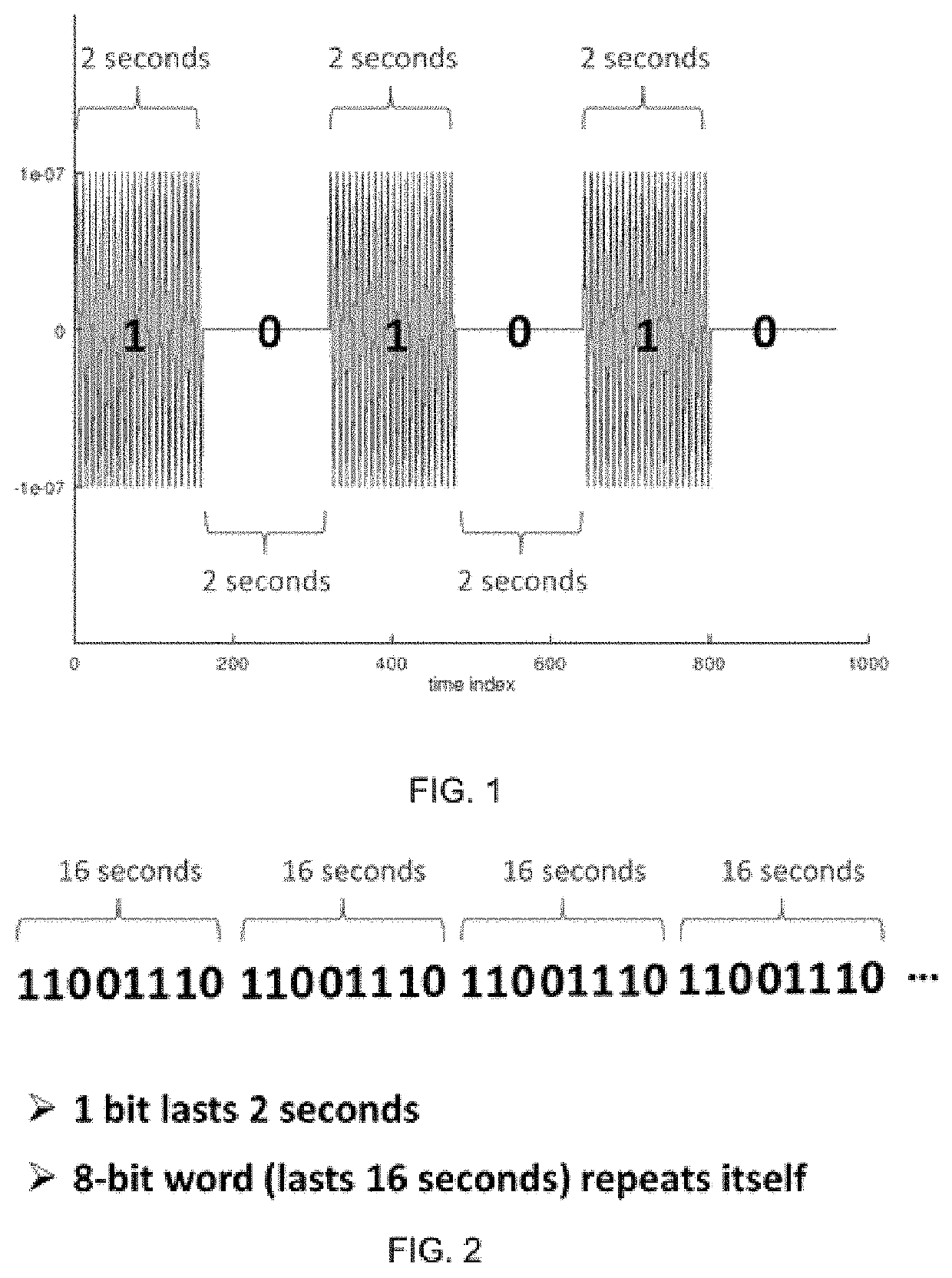
[0041]Where a signal is reflected by the ionosphere, see FIG. 16, the key items of certainty, assumption, and simulation, i.e. the starting point is Ionosphere average movement for phase change. Each bit lasts typically on the order of 1-8 seconds depending on the ionosphere movement probability distribution and frequency chosen. This varies across geographic regions, seasons, time of day, solar activity, and the 11 year solar cycle. FIG. 1 illustrates 8 bit transmission of 2 seconds. FIG. 2 shows the 8 bit transmission repeated at 2 seconds a bit. The faster the ionosphere movement the briefer the Time-enhanced Coherent Integration should be to recover the same signal. More transmissions and transmission time are needed for more non-coherent integrations to achieve the gain needed to detect and decode the signal. The average phase shift during a set of transmissions of a bit of information should be below around a maximum of + / −135 deg...


PUM


Abstract

An apparatus and method to transmit and receive messages within and near the noise floor by pulsed signals that are time synchronized and are not easily intercepted by use of frequency and time slots as well as intermittent transmissions.

Description

RELATED APPLICATION[0001]Provisional Application Ser. No. 62 / 867,789 filed Jun. 27, 2019 and Provisional Application No. 62 / 900,046 filed Sep. 13, 2019 that are incorporated by reference herein as if specifically set forth at length. Priority is claimed from Provisional Application No. 62 / 900,046.REFERENCE TO SEQUENCE LISTING, A TABLE, OR A COMPUTER PROGRAM LISTING COMPACT DISC APPENDIX[0002]N / AFEDERALLY SPONSORED RESEARCH OR DEVELOPMENT[0003]Army SBIR Phase II Contract No. W9124R-17-C-0012BACKGROUND OF INVENTION[0004]Radio communications in high noise environments typically require signal strength that is greater than the noise floor and also is generally insecure. This invention allows reconstruction of communication messages received at or far below the noise floor. This invention also has applicability to receive messages in highly attenuated environments such as deep within jungle canopy, when transmission power is relatively weak, or when the separation distance between transm...

Claims


Application Information

Patent Timeline
Patent Type & Authority Patents(United States)
IPC IPC(8): H04L7/00H04B17/336H04B1/16
CPCH04L7/0012H04B1/16H04B17/336H04L7/0037H04L7/0008H04W56/0035H04W56/001H04B7/22
Inventor CHORNENKY, TODD ERIC
Owner NOKOMIS
Why Eureka
Try Eureka