Purifying method and purifying device for argon gas

A purification method, argon technology, applied in separation methods, chemical instruments and methods, inert gas compounds, etc., can solve the problems of hydrogen residue, inability to argon purification, adsorption removal, etc., to reduce adsorption load, reduce purification load, The effect of lightening the load

Active Publication Date: 2012-12-05
SUMITOMO SEIKA CHEM CO LTD
View PDF7 Cites 1 Cited by
  • Summary
  • Abstract
  • Description
  • Claims
  • Application Information

AI Technical Summary

Problems solved by technology

Therefore, hydrogen cannot be adsorbed and removed in the subsequent adsorption treatment at normal temperature, so the hydrogen in the argon gas remains, and there is a problem that the argon gas cannot be purified with high purity.

Method used


Image

  • Purifying method and purifying device for argon gas
  • Purifying method and purifying device for argon gas
  • Purifying method and purifying device for argon gas

Examples


Embodiment 1

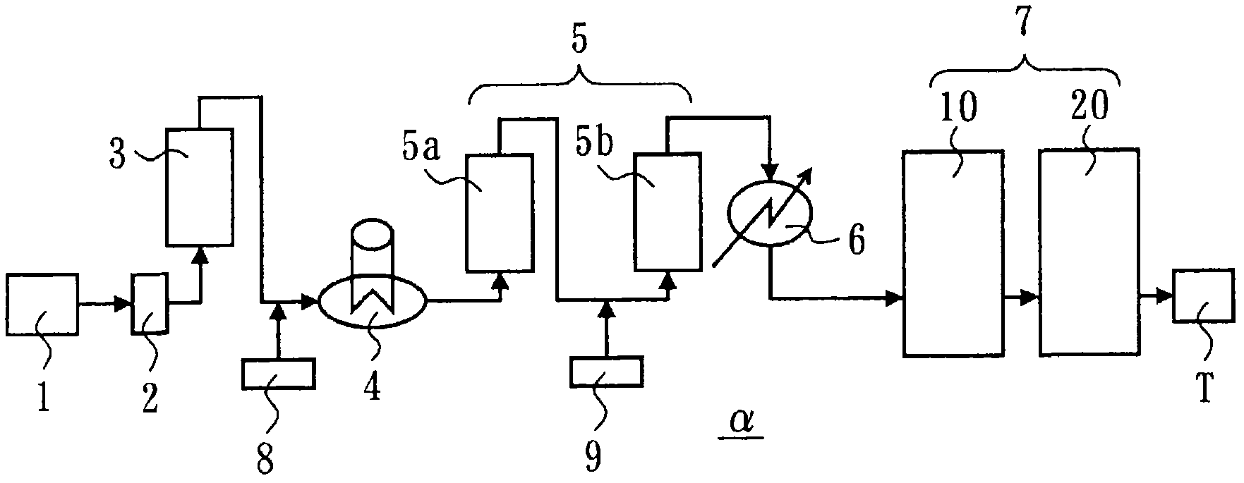
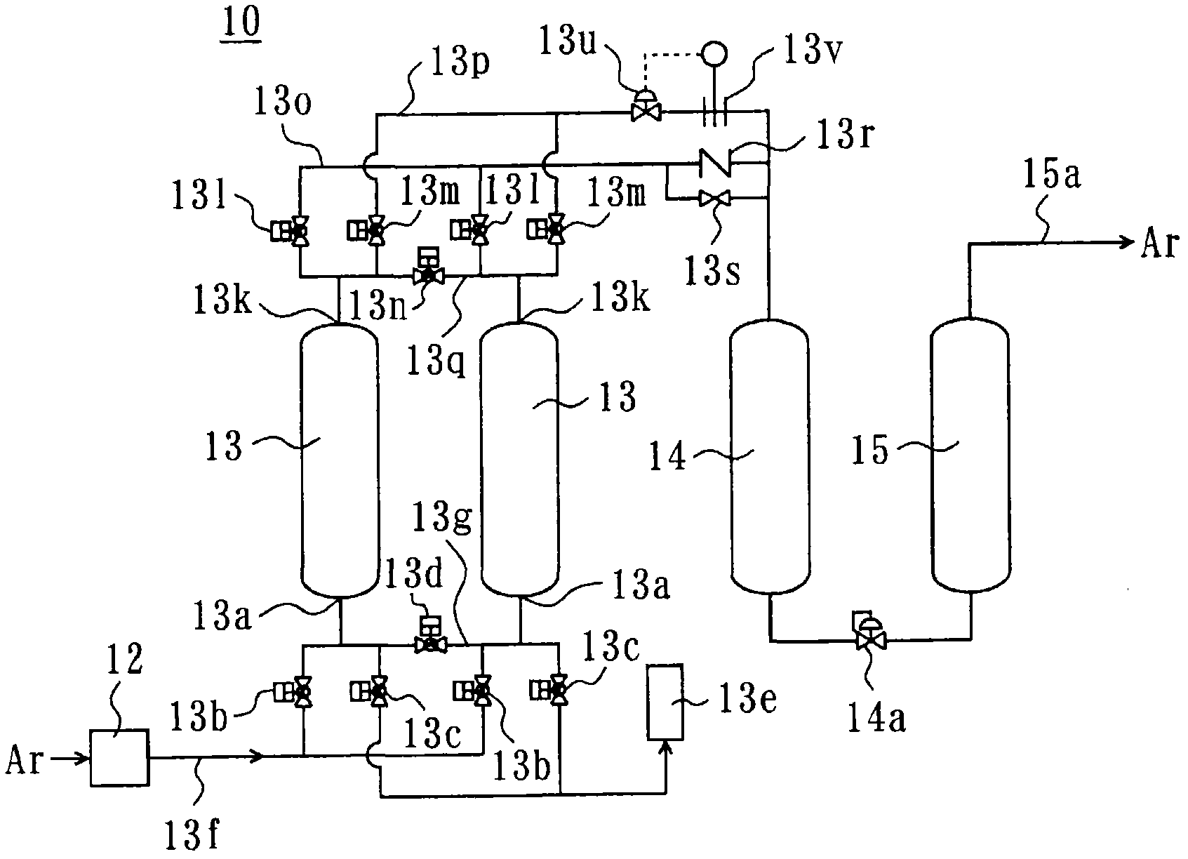
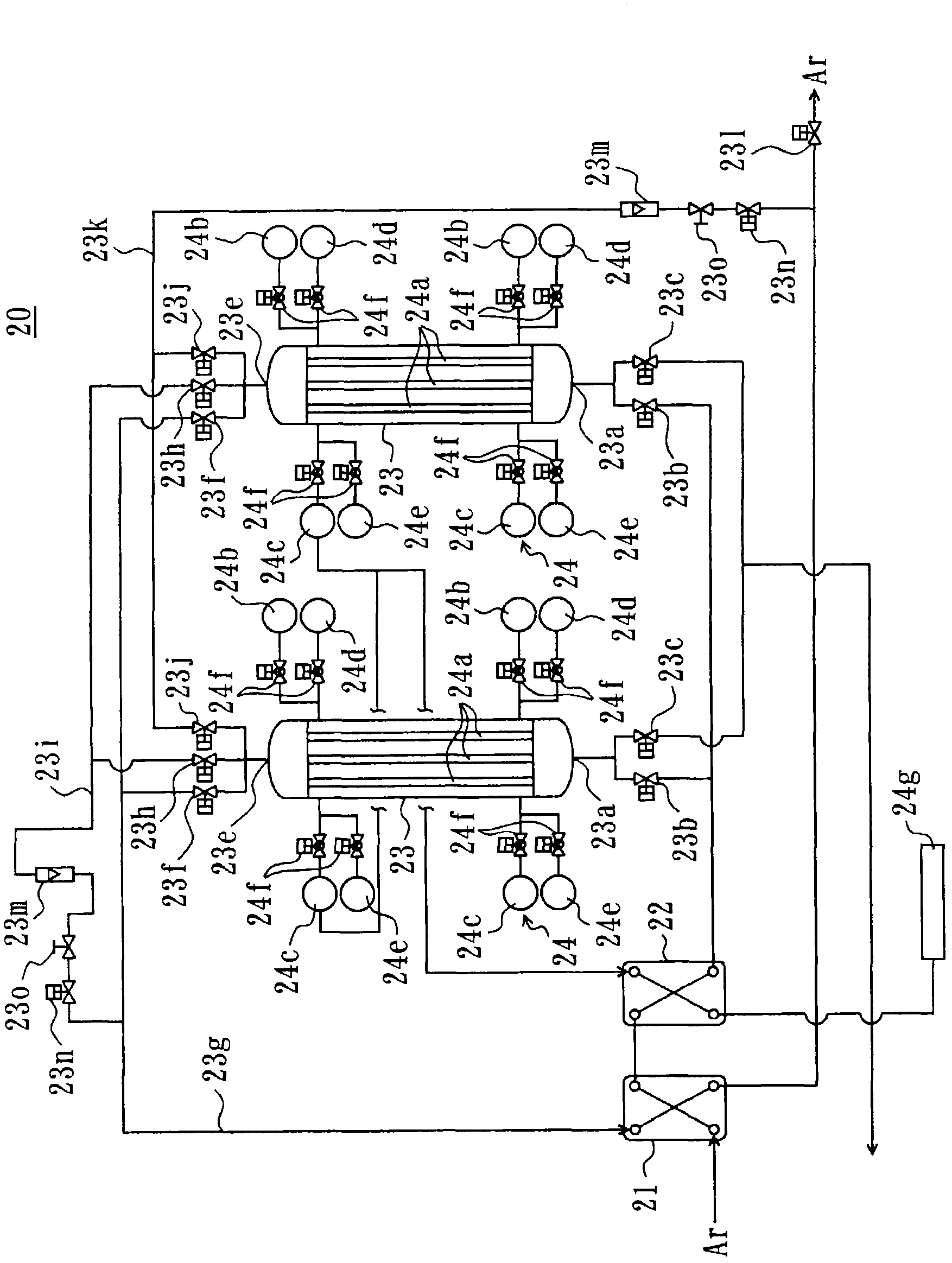
[0108] Purification of argon gas was performed using the purification apparatus α of the above-mentioned first embodiment. The argon gas before purification contains 300 mol ppm oxygen, 30 mol ppm hydrogen, 200 mol ppm carbon monoxide, 1200 mol ppm nitrogen, 10 mol ppm carbon dioxide, 10 mol ppm water, 10 mol ppm Methane as hydrocarbons, C2-C5 hydrocarbons at 20 mol ppm in terms of C1 hydrocarbons, 5 g / m 3 of oil. This argon is introduced into activated carbon adsorption tower 3 with the flow rate of 4.2L / min under the standard state. The activated carbon adsorption tower 3 is tubular with a nominal diameter of 32A, filled with 10 L of GX6 / 8 briquette manufactured by Nippon Environmental Chemicals Co., Ltd. Then, argon gas is introduced into the first reactor 5a. 50 mL of alumina-supported palladium catalyst (DASH-220D manufactured by N E Chem Kit Co., Ltd.) was filled in the first reactor 5 a, and the reaction conditions were set at a temperature of 350° C., atmospheric pr...

Embodiment 2

[0116] The oxygen concentration of the argon gas used for purification was 50 mol ppm, and the nitrogen concentration was 200 mol ppm, and oxygen was added to the argon gas from the oxygen supplier 8 at 1.1 ml / min before the first reactor 5a (so that the contained oxygen About 1.4 times the theoretical value required to react with hydrogen, carbon monoxide and hydrocarbons). Argon was purified under the same conditions as in Example 1 except that.

[0117] In this case, the impurity composition of the argon gas at the outlet of the activated carbon adsorption tower 3 and the outlet of the TSA unit 20 is as follows.

[0118] ·Activated carbon adsorption tower outlet

[0119] Hydrogen: 30 mole ppm, oxygen: 50 mole ppm, nitrogen: 200 mole ppm, carbon monoxide: 200 mole ppm, carbon dioxide: 10 mole ppm, water: 10 mole ppm, methane: 10 mole ppm, C2~C5 hydrocarbons: C1 hydrocarbons Converted to 15 mole ppm, oil content: not detected.

[0120] · TSA unit exit

[0121] Hydrogen: l...

Embodiment 3

[0123] The catalyst used in the second reactor 5b is palladium supported on alumina. Argon was purified under the same conditions as in Example 1 except that.

[0124] In this case, the impurity compositions of the argon gas at the outlet of the first reactor 5 a , the outlet of the second reactor 5 b , the outlet of the PSA unit 10 , and the outlet of the TSA unit 20 are shown in Table 1.


PUM


Abstract

The technical problem of the invention is to reduce the percentage of impurities of argon gas in a pre-treatment step of the adsorption treatment, reducing the power required by purification and purifying the argon gas with high purity. The technical scheme of the invention is that, a part of hydrocarbon and oil are absorbed by an activated carbon while purifying the argon gas containing oxygen, hydrogen, carbon oxide, hydrocarbon, oil and nitrogen; thereafter; if the amount of the oxygen in the argon gas is lower that a set amount of the oxygen required to react with all the hydrogen, the carbon oxide and the hydrocarbon, the oxygen is added so as to make the amount of oxygen to exceed the set amount, and enable the reaction by using catalyst; and then, the carbon oxide is added by an amount larger than a set amount required to react with all the residual oxygen of the aforementioned reaction, and ruthenium, palladium, or a catalyst of a mixture of the ruthenium and palladium is used to enable the reaction. Afterwards, the oxygen, the carbon oxide, carbon dioxide in the argon gas are adsorbed by an adsorbent through a pressure revolving adsorption method.

Description

technical field [0001] The present invention relates to a method and an apparatus for purifying argon gas containing at least oxygen, hydrogen, carbon monoxide, hydrocarbons, oil and nitrogen as impurities. Background technique [0002] In equipment such as silicon single crystal pulling furnaces, ceramic sintering furnaces, vacuum degassing equipment for steelmaking, silicon plasma melting equipment for solar cells, and polysilicon casting furnaces, argon is used as the furnace atmosphere gas and the like. The argon gas recovered from such equipment for reuse is degraded in purity due to the mixing of hydrogen, carbon monoxide, air, and the like. Therefore, in order to improve the purity of recovered argon gas, a process of adsorbing impurities to an adsorbent is performed. In addition, in order to efficiently perform such impurity adsorption, it has been proposed to make oxygen in impurities react with combustible components to convert them into carbon dioxide and water a...

Claims


Application Information

Patent Timeline
IPC IPC(8): C01B23/00B01D53/86B01D53/04B01D53/047
Inventor 坂本纯一山本守彦中谷光利尤珑志摩康一岸井充北岸信之
Owner SUMITOMO SEIKA CHEM CO LTD
Why Eureka
Try Eureka