Pre-assembled pulley device with elastic ring and method of installing same

An elastic ring and pulley technology, applied in shaft installation, hoisting device, bearing assembly, etc., can solve problems such as high cost

Inactive Publication Date: 2015-12-16
AB SKF
View PDF4 Cites 0 Cited by
  • Summary
  • Abstract
  • Description
  • Claims
  • Application Information

AI Technical Summary

Problems solved by technology

This leads to high cost
Also, when installing small elastic components such as circlips, they have a disturbing tendency to loosen elastically and pop out of the operator's line of sight or into a position they cannot access

Method used


Image

  • Pre-assembled pulley device with elastic ring and method of installing same
  • Pre-assembled pulley device with elastic ring and method of installing same
  • Pre-assembled pulley device with elastic ring and method of installing same

Examples


Embodiment Construction

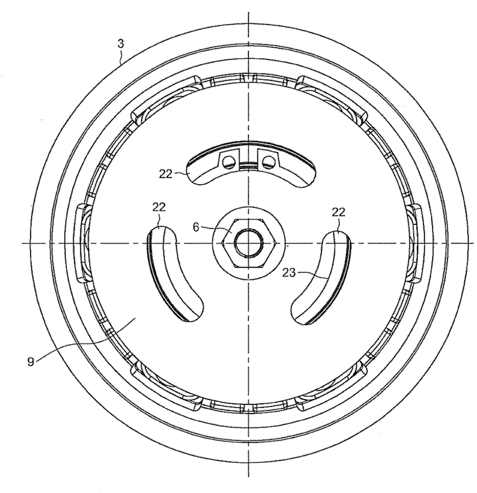
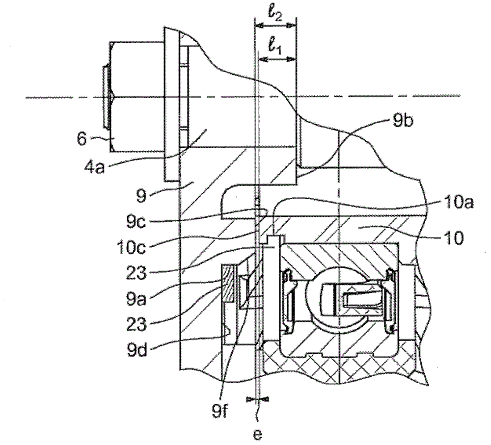
[0027] exist figure 1 and 2 In it, a pulley arrangement 1 is mounted on a compressor 2 comprising a non-rotating housing or shell 3 and a transfer spindle 4 rotatable about an axis 5 . The transfer mandrel 4 may be provided with a stepped end 4 a ending in a threaded portion so that it can interact with the nut 6 . This stepped end 4a, which is smaller in cross-section than the rest of the mandrel 4, is delimited by a shoulder 4b. The transfer mandrel 4 passes through the hollow shaft 10 of the housing coaxially with the transfer mandrel 4 . The shaft 10 of the housing has a radial end face 10c and a circumferential outer groove 10a adjacent to this end face 10c, that is to say the groove has an axial width greater than or equal to the distance between the end face 10c and the nearest edge of the groove 10a. The axial distance between the radial end face 10c of the shaft of the housing and the shoulder 4b of the mandrel 4 represents the algebraic distance l 1 ,Such as fig...


PUM

PropertyMeasurementUnit
lengthaaaaaaaaaa

Abstract

In a method for fitting a preassembled pulley subassembly (1) on a rotary machine (2), the preassembled subassembly comprising a pulley (7), a rolling bearing (8), a plate (9) and an elastic ring (23) positioned around a shoulder (9a) of the plate (9), the following steps are carried out:—the bearing (8) is mounted on a hollow shaft (10) of the rotary machine (2) and, at the same time, a hub (20) of the plate (9) is mounted on a rotary spindle (4) of the rotary machine (2), that passes through the hollow shaft (10),—the elastic ring (23) of the plate (9) is slid axially until it enters a groove (10a) in the hollow shaft (10) of the rotary machine.

Description

technical field [0001] The invention relates to a torque transmission device for use in particular in belt-driven rotary machines, such as motor vehicle air-conditioning compressors. Background technique [0002] In this compressor drive, a belt drive pulley drives the conveying spindle of the compressor via a drive plate. The pulley is mounted on the outer ring of the rolling bearing, and the inner ring of the rolling bearing is fixed to the hollow shaft of the compressor housing. A device of this type is described in detail in document FR2790521. [0003] However, the rolling bearing fitted with the pulley must be mounted on the compressor shaft, followed by the installation of the circlip (radially separated elastic ring) which axially secures the rolling bearing into a machined groove in the shaft of the shaft, and finally the drive plate. The number of operations performed under the assumptions of the manufacturer making the compressor is therefore high. These opera...

Claims


Application Information

Patent Timeline
Patent Type & Authority Patents(China)
IPC IPC(8): F16C35/073F16H55/36
CPCF16B41/002F16C13/006F16C19/163F16C35/073F16C2226/74F16C2361/63F16H55/36F16H57/0025Y10T29/49826F16C35/077
Inventor L.瓦诺克斯R.莱斯克莱尔
Owner AB SKF
Why Eureka
Try Eureka