Method for bonding circuit board reinforcing patches

A technology for reinforcing sheets and circuit boards, which is applied to printed circuits, printed circuit manufacturing, electrical components, etc., can solve the problems of low lamination efficiency, poor lamination accuracy, and high production costs, so as to save production costs and improve lamination. Accuracy, the effect of improving the bonding production efficiency

Inactive Publication Date: 2012-11-28
东莞森玛仕格里菲电路有限公司
View PDF3 Cites 23 Cited by
  • Summary
  • Abstract
  • Description
  • Claims
  • Application Information

AI Technical Summary

Problems solved by technology

Most of the current reinforcing sheets of flexible printed circuit boards are directly laminated by hand, which has low bonding efficiency and poor bonding accuracy. Most reinforcing materials such as aluminum sheets, steel sheets, ceramic sheets, etc. Adhesive, it can be used after additional processing of back glue, and the production cost is relatively high

Method used


Image

  • Method for bonding circuit board reinforcing patches
  • Method for bonding circuit board reinforcing patches
  • Method for bonding circuit board reinforcing patches

Examples


Embodiment 1

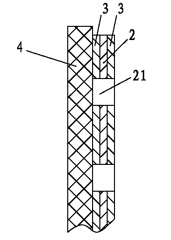
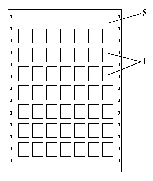
[0020] Embodiment 1: circuit board reinforcing sheet laminating method of the present invention, it comprises the following steps: A, the step of making adhesive layer 2: stick release paper 3 on the adhesive backed jig plate 4 that is drilled with positioning pin holes , and then attach the adhesive layer 2 that needs to be backed to the reinforcing sheet 1 on the release paper 3, and then use a laser cutting machine to open multiple windows 21 on the adhesive layer 2, and cut the adhesive layer 2 at the same time. out the positioning pin hole. The adhesive layer 2 is an adhesive tape or an adhesive sheet. A plurality of windows 21 are arranged in a matrix, and the size of the windows 21 is smaller than that of the reinforcing sheet 1 . The adhesive layer 2 can be a single-layer structure. After step A, only one side of the adhesive layer 2 has a layer of release paper 3; the adhesive layer 2 can also have a layer of release paper 3. There is a layer of release paper 3 on b...

Embodiment 2

[0025] Embodiment 2: The difference between this embodiment and Embodiment 1 is that the length of the receiving groove 61 is 1 mil longer than the length of the reinforcing sheet 1 , and the width of the receiving groove 61 is 1 mil larger than the width of the reinforcing sheet 1 .

Embodiment 3

[0026] Embodiment 3: The difference between this embodiment and Embodiment 1 is that the length of the receiving groove 61 is 3 mil longer than the length of the reinforcing sheet 1 , and the width of the receiving groove 61 is 3 mil larger than the width of the reinforcing sheet 1 .


PUM


Abstract

The invention relates to the technical field of circuit board processing, in particular to a method for bonding circuit board reinforcing patches. The method comprises the following steps of: A, bonding an adhesive layer onto release paper, and then processing a plurality of windows in the adhesive layer; B, bonding the adhesive layer to a reinforcing patch typesetting jig in a transfer manner by using a configuration reinforcing patch of the reinforcing patch typesetting jig so as to bond and fix the reinforcing patches and the adhesive layer, and cutting the surplus adhesive layer among the reinforcing patches to form a plurality of independent gummed reinforcing patches; and C, configuring the gummed reinforcing patches onto a reinforcing patch bonding jig according to positions, to be bonded with the reinforcing patches, on a circuit board, and bonding the circuit board onto the reinforcing patch bonding jig so as to bond and fix the reinforcing patches and the circuit board. According to the invention, by utilization of the jigs to assist bonding of the reinforcing patches, a plurality of reinforcing patches can be bonded in one step without manual single patch bonding, accurate alignment can be completed without manual precise alignment for bonding, so that the bonding precision of the reinforcing patches is improved, the making efficiency in bonding is improved greatly, and the making cost is saved.

Description

technical field [0001] The invention relates to the technical field of circuit board processing, in particular to a method for laminating reinforcing sheets of circuit boards. Background technique [0002] Flexible printed circuit boards are characterized by lightness, thinness and shortness, so they are prone to bends and scars during use; they have low mechanical strength and are easy to crack. Therefore, it is generally necessary to fit and reinforce it. The purpose of bonding reinforcement is to strengthen the mechanical strength of the circuit board and facilitate the surface mounting of parts. Most of the current reinforcing sheets of flexible printed circuit boards are directly laminated by hand, which has low bonding efficiency and poor bonding accuracy. Most reinforcing materials such as aluminum sheets, steel sheets, ceramic sheets, etc. Adhesives need to be used after additional processing of back glue, and the production cost is relatively high. Contents of t...

Claims


Application Information

Patent Timeline
IPC IPC(8): H05K3/00
Inventor 沈甘霖党新献杨志坚王平
Owner 东莞森玛仕格里菲电路有限公司
Why Eureka
Try Eureka