
Automatic method for external parameter joint calibration of vehicle-mounted three-dimensional laser radar and camera

A three-dimensional laser and joint calibration technology, which is applied in image data processing, instruments, radio wave measurement systems, etc., can solve problems such as manual errors, time-consuming, and low efficiency, so as to avoid errors, improve calibration accuracy, and improve simulation accuracy. The effect of precision

Pending Publication Date: 2020-10-09
JIANGSU UNIV
View PDF0 Cites 22 Cited by
  • Summary
  • Abstract
  • Description
  • Claims
  • Application Information

AI Technical Summary

Problems solved by technology

[0003] Among the existing camera and lidar joint calibration methods, some use stereo calibration boards, which require high manufacturing accuracy, complex manufacturing methods, and high costs; some use planar target calibration methods, but need to be recorded in the recorded data. Manually select the position of the feature points in the image pixels and the lidar point cloud. Manually selecting points will bring some manual errors. At the same time, selecting more feature points will take a certain amount of time and the efficiency is not high.

Method used


Image

  • Automatic method for external parameter joint calibration of vehicle-mounted three-dimensional laser radar and camera
  • Automatic method for external parameter joint calibration of vehicle-mounted three-dimensional laser radar and camera

Examples


Embodiment Construction

[0024] In order to make the purpose, technical solutions and advantages of the embodiments of the present invention clearer, the technical solutions in the embodiments of the present invention will be clearly described below in conjunction with the accompanying drawings in the embodiments of the present invention. Obviously, the described embodiments are the Some, but not all, embodiments are invented. Based on the embodiments of the present invention, all other embodiments obtained by persons of ordinary skill in the art without making creative efforts belong to the protection scope of the present invention.

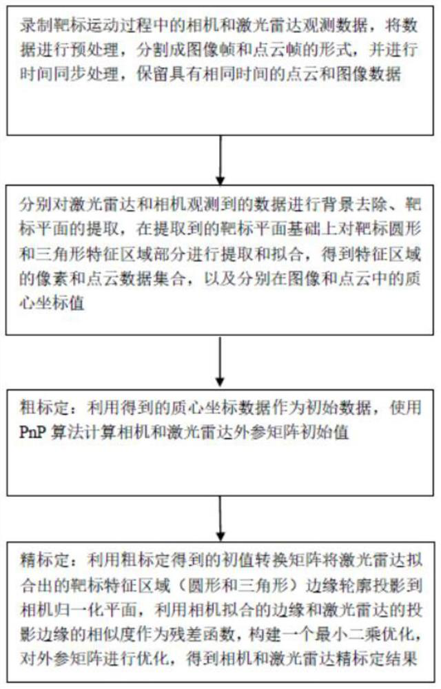
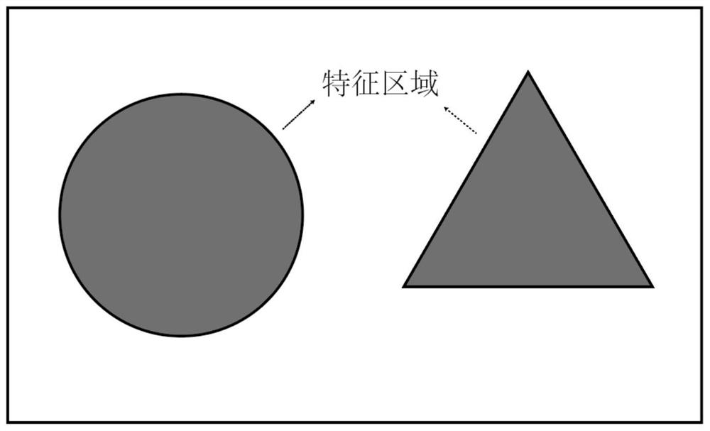
[0025] The invention realizes a joint calibration method of vehicle-mounted three-dimensional laser radar and camera external parameters, including three-dimensional laser radar and camera to be calibrated, a planar target with a special characteristic area and an industrial computer. The industrial computer is used to process the data when the target moves in the overl...


PUM


Abstract

The invention provides an automatic method for external parameter combined calibration of a vehicle-mounted three-dimensional laser radar and a camera. A laser radar and a camera are used to measure amoving plane target, a plurality of groups of point cloud and image data belonging to a target characteristic region are extracted from the measurement data; the characteristic region is fit, the external parameters of the laser radar and the camera are calibrated from coarse to fine by using a fitting result, and in coarse calibration, an initial conversion matrix between the laser radar and thecamera is obtained by using a PnP algorithm by using coordinates of a mass center point of the feature region fitted by the point cloud and the image as feature points; and fine calibration is carried out on the basis of coarse calibration, a feature region edge contour of point cloud fitting is projected to a camera normalization plane, a least square optimization function is constructed according to the similarity of a camera fitting edge and a projection edge, an initial conversion matrix is optimized, and a high-precision calibration relationship is obtained. Only the plane target with the special characteristic area is used, manual selection is not needed in the calibration process, and good calibration efficiency and accuracy are achieved.

Description

technical field [0001] The invention belongs to the technical field of equipment calibration, and in particular relates to an automatic method for joint calibration of vehicle-mounted three-dimensional laser radar and camera external parameters. Background technique [0002] At present, smart cars require the coordinated use of multiple sensors to effectively detect the environment, among which 3D lidar and camera are very important sensor combinations. The 3D lidar can effectively detect the 3D environment information, while the camera can better interpret the texture information in the environment. In order to combine the data of the two sensors, the lidar and the camera need to be calibrated in advance. [0003] Among the existing camera and lidar joint calibration methods, some use stereo calibration boards, which require high manufacturing accuracy, complex manufacturing methods, and high costs; some use planar target calibration methods, but need to be recorded in the...

Claims


Application Information

Patent Timeline
Patent Type & Authority Applications(China)
IPC IPC(8): G06T7/80G06T7/194G06T7/136G01S7/497
CPCG06T7/80G06T7/136G06T7/194G01S7/497G06T2207/10028G06T2207/10044
Inventor 蔡英凤陆子恒李祎承王海孙晓强袁朝春
Owner JIANGSU UNIV
Learn More