Electronic commutation electrically excited direct current motor

An electronic commutation, DC motor technology, used in electrical components, electromechanical devices, electric components, etc., can solve the problems of large dispersion of permanent magnet materials, increased motor costs, and rising prices of magnetic steel and magnetic tiles, so as to improve the climb rate. Slope capacity and overload capacity, improve overload capacity, the effect of simple and reasonable structure

Inactive Publication Date: 2012-11-28
马加良
View PDF4 Cites 3 Cited by
  • Summary
  • Abstract
  • Description
  • Claims
  • Application Information

AI Technical Summary

Problems solved by technology

However, in recent years, due to the rising price of permanent magnet materials, especially rare earth materials, the price of magnet steel and magnetic tiles has doubled, and the cost of motors has increased significantly. After completion, the magnetic flux of each pole and the air gap magnetic field cannot be adjusted. When the load exceeds the armature current, the operation is unstable, the overload capacity is poor, and it is easy to burn the machine.
Due to the above problems, the rapid development of brushless DC motors is difficult
[0005] For this reason, many manufacturers and people of insight have carried out fruitful development and research, but so far no reasonable products have come out.

Method used


Image

  • Electronic commutation electrically excited direct current motor
  • Electronic commutation electrically excited direct current motor
  • Electronic commutation electrically excited direct current motor

Examples


Embodiment Construction

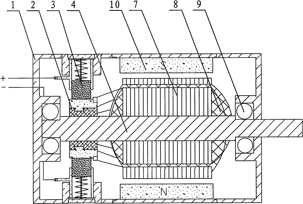
[0024] Figure 5 and Figure 6 Shown, for the present invention creates the first kind of specific embodiment of electronic commutation electric excitation DC motor, it comprises body 1, stator iron core 6, rotor iron core 7, rotating shaft 4, position sensor 11, sensing magnetic steel 15, The controller, the rotating shaft 4 is rotatably arranged on the body 1 through the bearing 9, the rotor core 7 is fixed on the rotating shaft 4, and the stator core 6 is provided with at least three sets of stator armature windings 12, and the rotor core 7 is At least one pair of rotor excitation windings 16 is provided, a collector ring 14 is fixed on the rotating shaft 4, a brush assembly 3 matched with the collector ring 14 is fixed on the body 1, and the two brushes of the brush assembly 3 are arranged on the circumference The same direction is in contact with the collector ring 14, of course, the two brushes can also be in contact with the collector ring 14 in the opposite direction ...


PUM


Abstract

The invention discloses an electronic commutation electrically excited direct current motor, which comprises a motor body (1), a stator core (6), a rotor core (7), a rotating shaft (4), a position sensor (11), sensing magnetic steel (15) and a controller, wherein the rotating shaft (4) is arranged on the motor body (1); the rotor core (7) is fixed on the rotating shaft (4); at least a pair of stator armature windings (12) is arranged on the stator core (6); at least a pair of rotor excitation windings (16) is arranged on the rotor core (7); a collector ring (14) is fixed on the rotating shaft (4); an electric brush assembly (3) is fixed on the motor body (1); the rotor excitation windings (16) are connected with the collector ring (14); and when load current exceeds a set value, the controller regulates the excitation voltage of the rotor excitation windings (16) according to the load current of the stator armature windings (12). By the structure, the motor has the advantages of simple and rational structure, working stability, high efficiency, high overload capability, high efficiency and the like.

Description

technical field [0001] The invention relates to a DC motor, in particular to an electrically excited DC motor that adjusts output torque by changing a magnetic field. Background technique [0002] At present, DC motors can be mainly divided into brushed electric excitation DC motors, brushed permanent magnet DC motors and brushless permanent magnet DC motors. [0003] The structure of a brush-excited DC motor is as follows: figure 1 As shown, it includes body 1, commutator 2, brush assembly 3, rotating shaft 4, stator field winding 5, stator core 6, rotor core 7, rotor armature winding 8, bearing 9, stator field winding 5 winding On the stator core 6 , the rotor armature winding 8 is wound on the rotor core 7 , and a magnetic field is established through the stator field winding 5 . Brushed permanent magnet DC motors such as figure 2 As shown, it includes body 1, commutator 2, brush assembly 3, rotating shaft 4, rotor core 7, rotor armature winding 8, bearing 9, magnetic...

Claims


Application Information

Patent Timeline
Patent Type & Authority Applications(China)
IPC IPC(8): H02K29/06H02K1/12H02K11/00H02K11/30
Inventor 马加良
Owner 马加良
Why Eureka
Try Eureka