Eureka AIR delivers breakthrough ideas for toughest innovation challenges, trusted by R&D personnel around the world.

Light source device and lighting device

A light source device and light source technology, applied to lighting devices, components of lighting devices, light sources, etc., can solve the problems of increased brightness and low heat dissipation efficiency

Inactive Publication Date: 2012-11-28
STANLEY ELECTRIC CO LTD
View PDF12 Cites 39 Cited by
  • Summary
  • Abstract
  • Description
  • Claims
  • Application Information

AI Technical Summary

Problems solved by technology

This means that the heat generated in the phosphor layer 92 is dissipated to the optical semiconductor element (fixed light source) 95 that also generates heat, resulting in low heat dissipation efficiency.
[0010] Thus, in figure 1 In the light source device of the present invention, the radiation efficiency of the heat generated in the transparent method and the phosphor layer 92 is low, which limits the increase in brightness.

Method used


Image

  • Light source device and lighting device
  • Light source device and lighting device
  • Light source device and lighting device

Examples


Embodiment Construction

[0032] Hereinafter, a light source device and a lighting device of the present invention will be described according to exemplary embodiments with reference to the accompanying drawings.

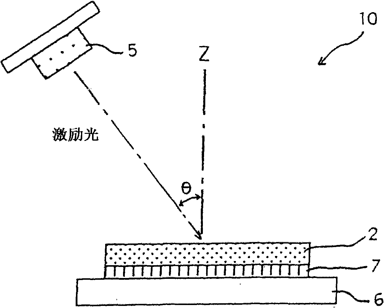
[0033] figure 2 A light source device described in an application (Japanese Patent Application No. 2009-286397) filed by the applicant of the present application and earlier than the application on which the present application is filed is shown. refer to figure 2 , the light source device 10 may include: a fixed light source 5 emitting light having a predetermined wavelength in a wavelength region covering ultraviolet light wavelengths and visible light wavelengths; and a phosphor layer 2 (wavelength conversion layer) containing at least one type of Phosphor material (wavelength conversion material), which is at least one type of phosphor material excited by excitation light from fixed light source 5 , emits fluorescence having a wavelength longer than that of light emitted from fixed li...


PUM

PropertyMeasurementUnit
wavelengthaaaaaaaaaa

Abstract

The invention relates to a light source device and a lighting device. The light source device can obtain a brightness much higher than the brightness obtained via the conventional mode, and comprises a fixed light source capable of emitting the light of a predetermined wavelength which is in wavelength regions of an ultraviolet light wavelength and a visible light wavelength; and a wavelength conversion layer comprising at least one type of phosphor material which come from the light excitation of the fixed light source, and emits the fluorescence of which the wavelength is longer than that of the light emitted from the fixed light source. The fixed light source and the wavelength conversion layer can be separated with each other in space, and the light source device can employ the mode of extracting at least part of fluorescence from the incidence plane of the wavelength conversion layer, wherein the excitation light comes from the fixed light source penetrates the incidence plane of the wavelength conversion layer to enter in the wavelength conversion layer. The wavelength conversion layer comprises a surface structure possessing depression or protrusion.

Description

technical field [0001] The present invention relates to a light source device and a lighting device. Background technique [0002] A light source device employing a combination of an optical semiconductor element such as an LED and a wavelength conversion layer such as a phosphor layer has been widely used. Such light source devices have been used in a wider range of fields including general lighting and headlights for vehicles due to recent trends toward higher brightness. Such a light source device is considered to provide a wider range of applications if its brightness can be continuously increased. [0003] The luminance of the aforementioned light source device employing a combination of an optical semiconductor element and a wavelength conversion layer can be improved by flowing a large current through the optical semiconductor element to increase the intensity of excitation light emitted from the optical semiconductor element. However, the actual situation is that h...

Claims


Application Information

Patent Timeline
Patent Type & Authority Applications(China)
IPC IPC(8): H01L33/50H01L33/20C04B35/44C04B35/50C04B35/58C04B35/515
CPCH01L33/50F21V9/16G02F1/00F21Y2101/02F21V13/08F21Y2115/10F21S41/16F21S41/176F21S41/32F21V9/30F21V9/45
Inventor 川上康之
Owner STANLEY ELECTRIC CO LTD
Why Eureka
Eureka Blog
Learn More