Method for generating test graph for detecting decoding circuit of memory
A technology for decoding circuits and test patterns, applied in static memory, instruments, etc., can solve the problem that test methods are not universal, and achieve the effect of saving test costs
- Summary
- Abstract
- Description
- Claims
- Application Information
AI Technical Summary
Problems solved by technology
Method used
Image
Examples
Embodiment 1
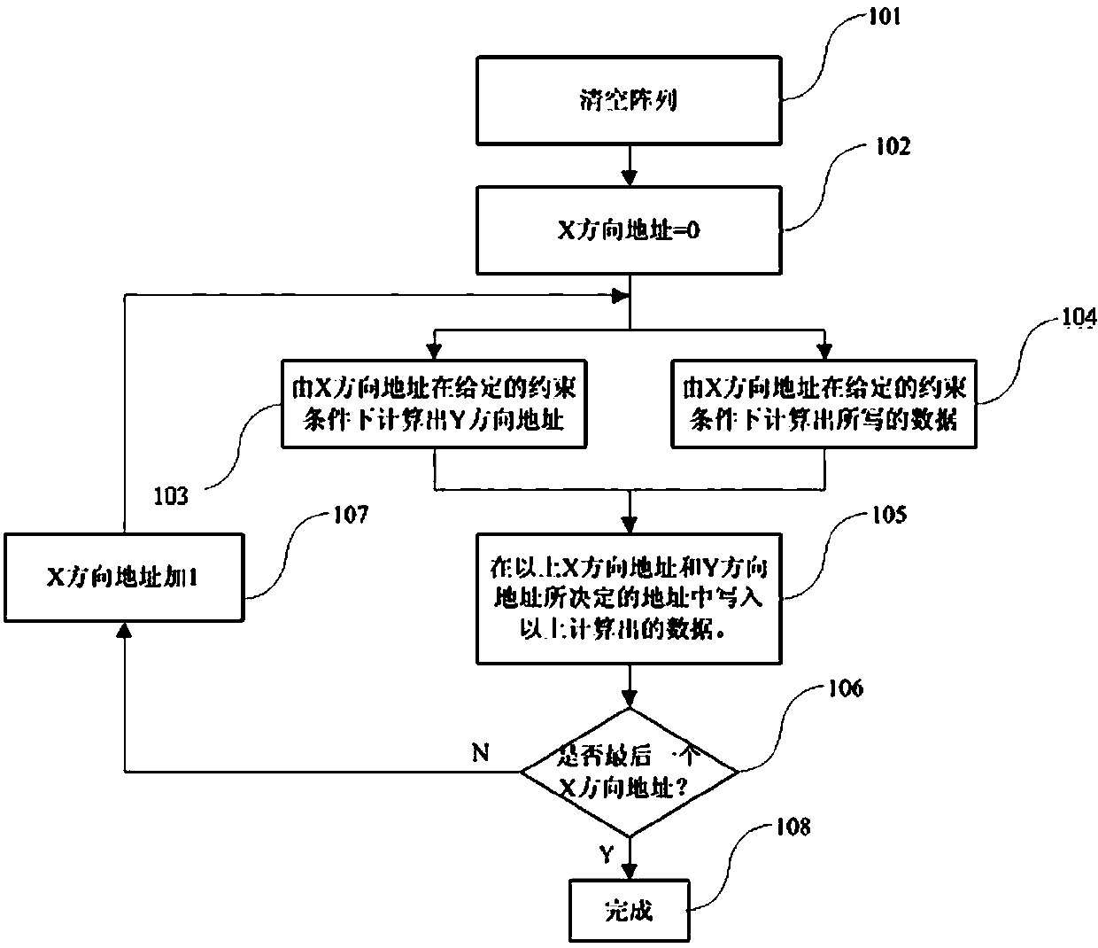
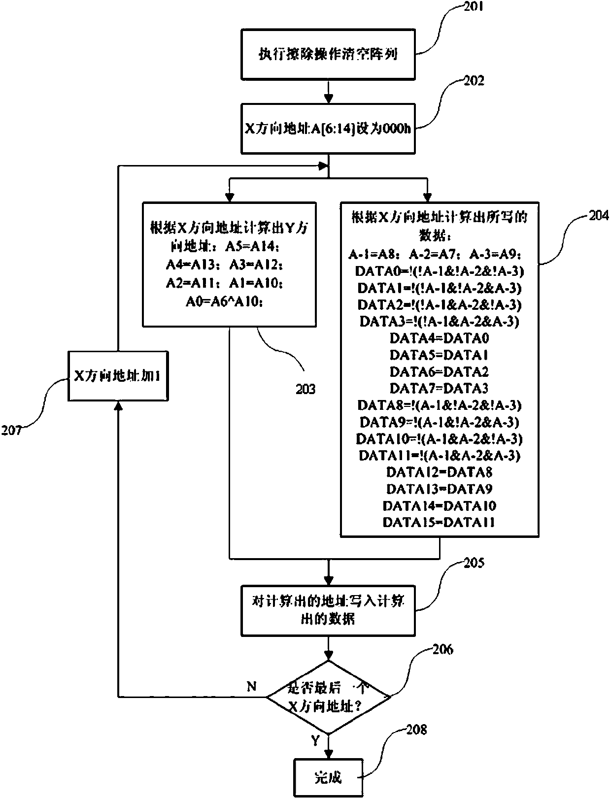
[0039] The full address of a NOR FLASH memory storage array is A[0:14]; the address of the decoding circuit in the X direction is A[6:14], and 512 WORDLINEs are decoded; the address of the decoding circuit in the Y direction is A[0 :5], 64 WORDs are decoded, and each WORD has a bit width of 16 bits, so there are 64*16=1024 BITLINEs in total. The storage array can be divided into two square arrays (each array is 512*512), the data DATA0~DATA3 and DATA7~DATA10 are located in the square array A, and the data DATA4~DATA7 and DATA8~DATA15 are located in the square array array B. The schematic diagram of the array address is as follows Figure 5 shown. If the array is erased, all BITs are in a 1 state; if a BIT is selected for programming, it is in a 0 state. The principle of generating the checkerboard test pattern is that when A0^A6^A10=0 (^ means XOR), the WORD will be programmed with the data of 0000h, otherwise the WORD will remain in the erased state of FFFFh.
[0040] The...
Embodiment 2
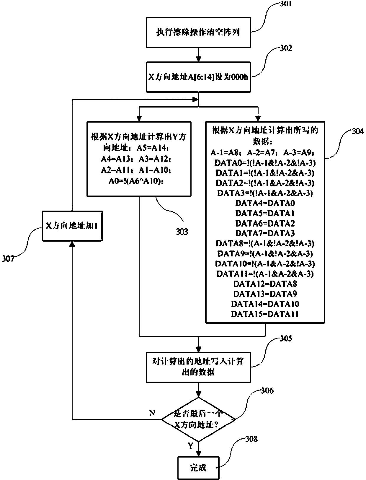
[0072] Embodiment 2: the full address of a NOR FLASH memory storage array is A[0:14]; the address of the decoding circuit in the X direction is A[6:14], and 512 WORDLINEs are decoded; the address of the decoding circuit in the Y direction It is A[0:5], 64 WORDs are decoded, and each WORD has a bit width of 16 bits, so there are 64*16=1024 BITLINEs in total. The storage array can be divided into two square arrays (each array is 512*512), the data DATA0~DATA3 and DATA7~DATA10 are located in the square array A, and the data DATA4~DATA7 and DATA8~DATA15 are located in the square array array B. The schematic diagram of the array address is as follows Figure 5 shown. If the array is erased, all BITs are in a 1 state; if a BIT is selected for programming, it is in a 0 state. The principle of generating the test pattern of the reverse checkerboard is that when A0^A6^A10=1 (^ means XOR), the WORD will be programmed with the data of 0000h, otherwise the WORD will remain in the erase...
PUM
 Abstract
Description
Claims
Application Information
 - Generate Ideas
- Intellectual Property
- Life Sciences
- Materials
- Tech Scout
- Unparalleled Data Quality
- Higher Quality Content
- 60% Fewer Hallucinations
Browse by: Latest US Patents, China's latest patents, Technical Efficacy Thesaurus, Application Domain, Technology Topic, Popular Technical Reports.
© 2025 PatSnap. All rights reserved.Legal|Privacy policy|Modern Slavery Act Transparency Statement|Sitemap|About US| Contact US: help@patsnap.com


