System for treating sulfur residue

A technology of sulfur slag and sulfur incineration furnace, which is applied in the direction of sulfur compounds, inorganic chemistry, non-metallic elements, etc., can solve the problems of high investment cost and low investment in additional equipment, and achieve the effect of convenient disassembly and cleaning, low investment and long service life

Active Publication Date: 2012-11-28
宜宾海翔化工有限责任公司 +1
View PDF6 Cites 1 Cited by
  • Summary
  • Abstract
  • Description
  • Claims
  • Application Information

AI Technical Summary

Problems solved by technology

The present invention utilizes the existing sulfur acid production system, and by adding a combustion furnace and a flue, overcomes the technical problem of high investment cost of additional equipment in the prior art, and can burn the original accumulated sulfur slag to convert sulfur dioxide gas for use in Production of sulfuric acid, turning waste into wealth, reducing the input of sulfur raw materials; less investment, saving costs

Method used


Image

  • System for treating sulfur residue
  • System for treating sulfur residue
  • System for treating sulfur residue

Examples


Embodiment 1

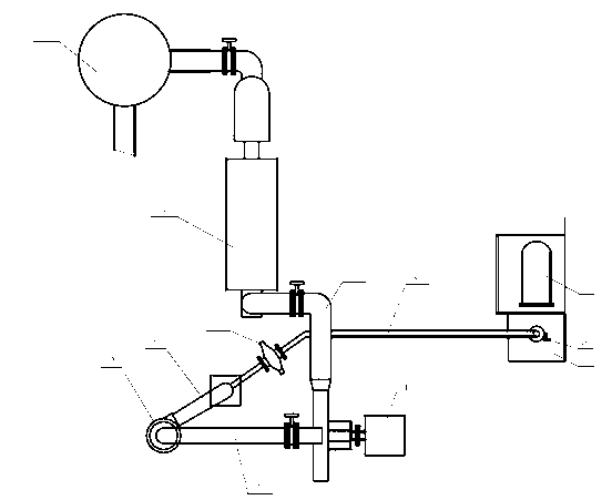
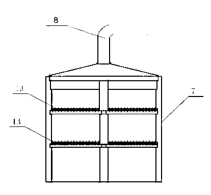
[0030] A system for processing sulfur slag, comprising a fan 1, a drying tower 2 and a sulfur incinerator 3, the fan 1 is provided with an air inlet pipe 4 and an air outlet pipe 5, the outlet of the sulfur incinerator 3 and the fan 1 The air pipe 5 is connected, and the drying tower 2 is connected with the air inlet pipe 4 of the fan 1. The drying tower 2 is provided with a suction pipe 6, and the suction pipe 6 is provided with a suction port, and also includes a combustion furnace 7 and a flue 8 , One end of the flue 8 communicates with the combustion furnace 7 , and the other end communicates with the suction pipe 6 .

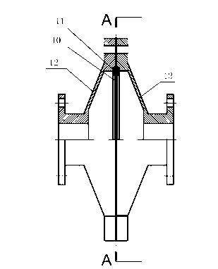
[0031] In the present invention, the flue 8 is provided with a filter 9, the filter 9 includes a housing, a filter screen 10 and a pressure plate 11, a filter cavity is provided inside the housing, and the filter screen 10 and the pressure plate 11 are all provided In the filter cavity, the filter cavity communicates with the flue 8 .

[0032] In the prese...

Embodiment 2

[0042] The difference from Embodiment 1 is that a sulfur filter 14 is provided on one side of the combustion furnace 7 .

[0043]When the present invention is in use, it can overcome the situation that the sulfur slag produced by the equipment in the prior art occupies the site, and the sulfur slag discharge place of the combustion furnace 7 is next to the sulfur filter 14, which is convenient for treating the sulfur slag; at the same time, it solves the problem of natural discharge of the sulfur slag potential safety hazards and environmental pollution.

Embodiment 3

[0045] The difference from Embodiments 1 and 2 is that: the combustion furnace 7 is provided with a three-layer furnace bridge 13; the filter screen 10 is one layer, and the pressing plate 11 is two pieces; the filter screen 10 is fixed between the two pressing plates 11 Between, filter screen 10 is compressed by two pressing plates 11.


PUM


Abstract

The invention discloses a system for treating sulfur residue. The system comprises a fan, a drying tower and a sulfur burning furnace, wherein the fan is provided with an air charge pipe and an air discharge pipe, the sulfur burring furnace is communicated with the air discharge pipe of the fan, the drying tower is communicated with the air charge pipe of the fan, the drying tower is provided with an air absorption pipe, and the air absorption pipe is provided with an exhaust opening. The system further comprises a combustion furnace and a flue, wherein one end of the flue is communicated with the combustion furnace, and the other end of the flue is communicated with the air absorption pipe. Through utilizing the traditional sulfur acid-making production system, the combustion furnace and the flue are additionally provided so that a technical problem of large investment cost of the additional devices in the prior art is overcome, and originally stacked sulfur residue can be combusted to be conversed to sulfur dioxide gas; and in addition, the system disclosed by the invention is used for producing the sulfuric acid, changes waste into wealth, reduces the investment of sulfur raw materials, has low investment and saves the cost.

Description

technical field [0001] The invention relates to the field of sulfur acid production systems, in particular to a system for treating sulfur slag. Background technique [0002] During the melting sulfur refining process of sulfur, the filter continuously filters the crude sulfur. While filtering out the impurities in the liquid sulfur, part of the sulfur is also discharged with the filter residue. The filter residue is analyzed and found to contain sulfur. The amount reaches 70%; since it was put into production, the treatment of filter residues has been sent out, and the company has to pay a certain amount of environmental protection fees every year; on the one hand, sulfur residues cause high sulfur cost investment; on the other hand, if they are discharged naturally, sulfur residues will contact fire sources It is flammable, endangers the environment and poses a safety hazard. [0003] Treatment of sulfur slag in the prior art The sulfur slag is sold to the sulfur gold s...

Claims


Application Information

Patent Timeline
Patent Type & Authority Applications(China)
IPC IPC(8): C01B17/54
Inventor 尹继国唐金钟黄萍王毅罗斌方难生
Owner 宜宾海翔化工有限责任公司
Why Eureka
Try Eureka