Camshaft arrangement structure of multi-functional gas distribution mechanism test stand

A gas distribution mechanism and camshaft technology, which is applied in the testing of machine/structural components, engine testing, valve devices, etc., can solve the problems of long camshaft processing cycle, high cost, and high complexity of test benches, etc., to achieve The effect of shortening the processing cycle, high reuse rate and cost saving

Inactive Publication Date: 2012-11-21
NO 70 INST OF CHINA NORTH IND GRP
View PDF6 Cites 2 Cited by
  • Summary
  • Abstract
  • Description
  • Claims
  • Application Information

AI Technical Summary

Problems solved by technology

[0004] The purpose of the present invention is to solve the problems of excessive complexity of the test bench, long camshaft processing cycle and high cost when the gas distribution mechanism test bench adopts the whole machine camshaft structure

Method used


Image

  • Camshaft arrangement structure of multi-functional gas distribution mechanism test stand

Examples


Embodiment Construction

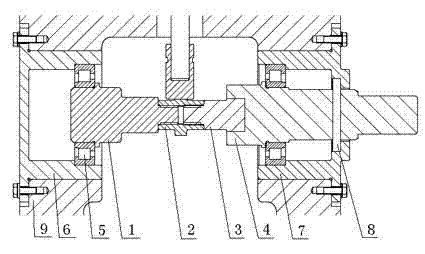
[0027] A camshaft arrangement structure of a multifunctional valve mechanism test bench, mainly including a camshaft support module, a cam module, a transmission module, a transmission coupling shaft, a rolling bearing, a rear thrust bearing sleeve, a front thrust bearing sleeve, a sealing ring, a support Parts such as the box body, among which, the camshaft is composed of the support module, the cam module and the transmission module; the cam module is respectively connected with the support module and the transmission module in the form of precision threads, the tightening torque is constant, and the thread screwing direction needs to be consistent with the The camshafts rotate in the same direction;

[0028] The two rolling bearings that provide support for the camshaft are located at both ends of the camshaft, one at each end; the rear thrust bearing sleeve and the front thrust bearing sleeve that jointly control the axial movement of the camshaft are respectively matched w...


PUM


Abstract

The invention discloses a camshaft arrangement structure of a multi-functional gas distribution mechanism test stand, which mainly includes a camshaft support module (1), a cam module (2) and a transmission module (3), as well as parts including a transmission coupling shaft (4), a rolling bearing (5), a rear thrust bearing bush (6), a front thrust bearing bush (7), a seal ring (8) and a support box body, wherein the support module (1), the cam module (2) and the transmission module (3) form the camshaft; the rear thrust bearing bush (6) and the front thrust bearing bush (7) are respectively connected with the rolling bearing (5) on respective sides thereof in a matched manner; the transmission module (3) and the transmission coupling shaft (4) are connected; and further, the seal ring (8) playing the sealing effect is positioned on the outer side at the end part of the transmission coupling shaft (4) in a nested manner. The camshaft disclosed by the invention adopts the module combination manner, so that the processing period is short; materials of all modules can be selected and matched freely; the reuse ratio is high, so that the cost is saved; and the supporting, thrusting, lubricating and sealing ways are simple and direct.

Description

technical field [0001] The invention belongs to the technical field of engines, and in particular relates to a camshaft arrangement structure of a multifunctional valve mechanism test bench. Background technique [0002] The valve train is an important part of the engine, and whether its design is good or not directly affects the performance index of the engine. Therefore, in the engine pre-research or prototype stage, it is very important to establish a multi-functional valve train test bench that can carry out valve train friction and wear, stiffness measurement, stress test and kinematics and dynamics simulation verification. [0003] As the main driving part of the engine valve train, the layout design of the camshaft is very important. Generally, the camshaft used in the valve train test bench generally adopts the whole machine camshaft structure, and the arrangement method also follows the whole machine camshaft arrangement. In this way, on the one hand, the complexi...

Claims


Application Information

Patent Timeline
Patent Type & Authority Applications(China)
IPC IPC(8): G01M15/02F01L1/047
Inventor 陈闯彭海雄王小慧侯晔星刘宇强刁占英卫军朝
Owner NO 70 INST OF CHINA NORTH IND GRP
Why Eureka
Try Eureka