Aiming device for microscope for plasma diagnosis and use method thereof

A aiming device and plasma technology, applied in microscopes, installations, telescopes, etc., can solve problems such as complex mechanical structures, high axial positioning accuracy, and complex structures, and achieve the effect of simplifying the system structure and improving aiming accuracy

Inactive Publication Date: 2012-11-14
TONGJI UNIV
View PDF6 Cites 5 Cited by
  • Summary
  • Abstract
  • Description
  • Claims
  • Application Information

AI Technical Summary

Problems solved by technology

[0008] This aiming method mainly has the following two disadvantages: 1. In order to achieve high-precision aiming, a lens with a large numerical aperture is needed, and the structure is complicated; 2. The imaging equipment independent of the extreme ultraviolet optical system will occupy the space in the target cavity of the powerful laser device. limited space
However, the aiming scheme in this invention patent has the following disadvantages: 1. The key components of aiming are two telephoto optical imaging lenses, so the axial aiming accuracy depends on the depth of field of the telephoto lens and the angle between the two telephoto lenses , the axial positioning accuracy is high when the depth of field is small and the included angle is large, and the axial positioning accuracy is low when the depth of field is large and the included angle is small, so the axial (Z direction) aiming accuracy of the aiming method described in the patent is ±100 μm
The advantage of this method is that the positioning accuracy is high and the reliability is strong, but the positioning ball needs to be retracted in the experiment, which requires a more complicated mechanical structure to realize. In addition, the positioning ball is very easy to be damaged, and once damaged, the positioning ball needs to be reset. calibration

Method used


Image

  • Aiming device for microscope for plasma diagnosis and use method thereof
  • Aiming device for microscope for plasma diagnosis and use method thereof
  • Aiming device for microscope for plasma diagnosis and use method thereof

Examples


Embodiment

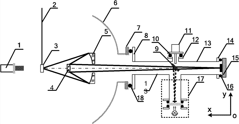
[0035] The present invention adopts the mode of visible light twice imaging to realize the precise aiming of the system to the target point in the vacuum chamber.

[0036]In the present invention, the key positioning device is the microscope 1, whose magnification can be selected as 50-100 times, and the numerical aperture is 0.2-0.25. The depth of field determines the positioning accuracy of the system in the axial x direction, and the magnification determines the vertical optical axis. The positioning accuracy of the direction, its depth of field satisfies:

[0037] Δ = 1 2 λ ( NA ) 2

[0038] λ is the wavelength of visible light, with a value of 540nm, and NA is the numerical aperture of the positioning microscope 1 for positioning. Therefore, the depth of field of the positioning microscope is...


PUM


Abstract

The invention relates to an aiming device for a microscope for plasma diagnosis and a use method thereof. The aiming device comprises a line gatherer, a plane mirror, a luminous source, a glass plate and a grid plate. The line gatherer is connected with a short connecting pipe arranged on a vacuum pipeline through a flange piece, the plane mirror is arranged in the vacuum pipeline and connected with the line gatherer capable of driving the plane mirror to lead in and lead out, the grid plate is adhered to the glass plate, and the glass plate with the grid plate is arranged at one end of a long connecting pipe communicated with the vacuum pipeline and fixed through a flange cover. According to the method, a reverse imaging method is adopted, an image distance of an image system is first determined, and an object point is located through the microscope with small depth of field. Compared with the prior art, the aiming device and the use method of the aiming device have the advantages that a device structure is simple, a use method is easy, aiming precision is high, normal work of other diagnosis devices in a strong-laser device target cavity can not be affected and the like.

Description

technical field [0001] The invention relates to the field of microscopes for plasma diagnosis, in particular to a microscope aiming device for plasma diagnosis and an application method thereof. Background technique [0002] In the plasma diagnostic experiment, the coincidence of the optimal object point of the imaging system and the target is related to the success or failure of the diagnostic experiment. The aiming of the imaging system to the target point has two aspects, one is to make the target point on the optical axis of the system, and the other is to ensure that the target point is within the depth of field allowed by the imaging spatial resolution of the system. [0003] The extreme ultraviolet Schwarzschild (Schwarzschild) microscope used in the intense laser plasma diagnosis experiment is a normal incidence reflective imaging device, and its objective lens is composed of two concentric spherical mirrors, such as figure 1 As shown, the primary mirror 5 is a conc...

Claims


Application Information

Patent Timeline
Patent Type & Authority Applications(China)
IPC IPC(8): G02B21/00G02B23/00G02B7/00
Inventor 穆宝忠王新王占山黄怡伊圣振
Owner TONGJI UNIV
Why Eureka
Try Eureka