Driving device for oil pump

A driving device and oil pump technology, applied in the direction of machines/engines, pumps, pump components, etc., can solve the problems of complex transmission system, low work efficiency, difficult assembly, etc., and achieve simplified transmission system, high work efficiency and simple installation Effect

Inactive Publication Date: 2012-11-14
NO 70 INST OF CHINA NORTH IND GRP
View PDF5 Cites 3 Cited by
  • Summary
  • Abstract
  • Description
  • Claims
  • Application Information

AI Technical Summary

Problems solved by technology

[0003] The purpose of the present invention is to solve the problems that the existing internal combustion engine oil pump driving device is driven by gears, the transmission system is complicated, the assembly is difficult, and the work efficiency is low. The purpose is to provide an oil pump driving device with simplified transmission, simple assembly and high work efficiency.

Method used


Image

  • Driving device for oil pump

Examples


Embodiment Construction

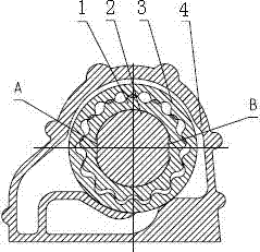
[0014] A driving device for an oil pump, including an inner rotor, a crankshaft, an outer rotor, and an oil pump volute. The inner rotor of the oil pump is set on the crankshaft through positioning surfaces A and B, the outer rotor is inlaid on the inner rotor, and the outermost is the machine The oil pump volute; the positioning surfaces A and B are used to prevent the relative rotation of the crankshaft and the inner rotor, and the crankshaft can directly drive the inner rotor of the oil pump to rotate to deliver high-pressure oil; the maximum fit clearance between the joint surfaces A and B of the crankshaft and the inner rotor 0.1mm, if possible, 0.03-0.1mm.


PUM


Abstract

The invention discloses a driving device for an oil pump. The driving device comprises an inner rotor (1), a crankshaft (2), an outer rotor (3) and an oil pump volute (4). The driving device is characterized in that the inner rotor (1) of the oil pump is arranged on the crankshaft (2) through a positioning surface A and a positioning surface B, the outer rotor (3) is sleeved on the inner rotor (1) in an embedded manner, the oil pump volute (4) is positioned on the outermost side, the positioning surface A and the positioning surface B are used for stopping relative rotation of the crankshaft (2) and the inner rotor (1), the inner rotor (1) of the oil pump can be directly driven to rotate by the crankshaft (2) so that high-pressure oil is delivered, and the maximum fit clearance between a joint surface A and a joint surface B of the crankshaft (2) and the inner rotor (1) is 0.1mm, for example, the fit clearance can range from 0.03mm to 0.1mm. By the aid of the driving device, a transmission system can be simplified, transmission space is saved, a gear and a central shaft of the oil pump are omitted, the production cost of an engine is saved, and the driving device is simple to mount and high in working efficiency.

Description

technical field [0001] The invention belongs to the technical field of internal combustion engines, is a part of the internal combustion engines, and in particular relates to a driving device of an oil pump. Background technique [0002] At present, the drive of the oil pump of the internal combustion engine is mostly driven by gear transmission first, and then drives the oil pump. The transmission system is relatively complicated, the gears are meshed with each other, the assembly is difficult, and the work efficiency is low. Contents of the invention [0003] The present invention aims to solve the problems that the existing internal combustion engine oil pump driving device is driven by gears, the transmission system is complicated, the assembly is difficult, and the working efficiency is low. The purpose is to provide an oil pump driving device with simplified transmission, simple assembly and high working efficiency. [0004] Technical scheme of the present invention...

Claims


Application Information

Patent Timeline
Patent Type & Authority Applications(China)
IPC IPC(8): F04C15/00F04C2/10
Inventor 马军华任伟魏志明陈晓飞赵志芳张全中胡定云白军爱王红丽舒涌任贵峰谭建松
Owner NO 70 INST OF CHINA NORTH IND GRP
Why Eureka
Try Eureka