
Pulse-taking signal sensor probe and optical fiber pulse-taking information acquisition system

A signal sensor and pulse diagnosis technology, which is applied in the field of optical fiber pulse diagnosis information collection system, can solve the problems of low sensitivity, reduced accuracy and sensitivity, and large volume, so as to reduce the damage rate of equipment, prevent skin from being pierced, and improve the use of The effect of longevity

Active Publication Date: 2012-11-14
济宁高新科达科技项目服务有限公司
View PDF6 Cites 23 Cited by
  • Summary
  • Abstract
  • Description
  • Claims
  • Application Information

AI Technical Summary

Problems solved by technology

The existing commercially available sensors are basically piezoresistive sensors. The common problems are that the volume is too large, the sensitivity is low, and the tactile sensation of fingers cannot be accurately simulated. will further reduce the accuracy and sensitivity

Method used


Image

  • Pulse-taking signal sensor probe and optical fiber pulse-taking information acquisition system
  • Pulse-taking signal sensor probe and optical fiber pulse-taking information acquisition system
  • Pulse-taking signal sensor probe and optical fiber pulse-taking information acquisition system

Examples


Embodiment 1

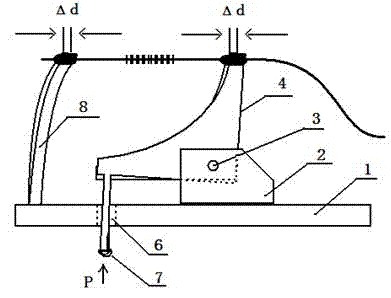
[0066] like Figure 2-3 As shown, a pulse diagnosis signal sensor probe includes a base 1 and a rotating shaft support seat 2 and an elastic beam 8 arranged on the base 1. A shaft hole 3 is arranged on the rotating shaft support seat 2 and a shaft hole 3 is arranged on the shaft hole 3. The middle part of the link 4 is hinged on the support seat 2 of the rotating shaft through the rotating shaft and can pivot around the rotating shaft. The link 4 includes two parts: a cross arm and a longitudinal arm, and one end of the cross arm is connected to the lower end of the longitudinal arm. Together, one end of the fiber grating is fixed on the upper end of the longitudinal arm, and the other end of the fiber grating is fixed on the top of the elastic beam 8; a probe 5 is set at the other end of the cross arm of the linkage member, and the probe 5 passes through the through hole set on the base 1 Extends beyond base 1.

[0067] The rotating shaft is horizontally arranged in the shaf...

Embodiment 2

[0074] like figure 1 As shown, a pulse diagnosis information collection system, which includes a broadband light source with optical fiber coupling output, a spectrum measuring instrument, the broadband light source and the spectrum measuring instrument are connected to one side of the fiber coupler at the same time, and the other side of the fiber The diagnostic signal sensor probe is connected, and the spectrometer is electrically connected with the computer. The same content of the pulse diagnosis signal sensor probe as in Embodiment 1 will not be repeated.

[0075] The broadband light source emits wide-spectrum light, which reaches the probe through the optical fiber coupler and optical fiber. The probe converts the pulse information into optical information and reflects it back to the optical fiber coupler. After passing through the optical fiber coupler, it enters the spectrometer, and the spectrometer converts the optical information into electrical information. , ana...


PUM

PropertyMeasurementUnit
Diameteraaaaaaaaaa

Abstract

A pulse-taking signal sensor probe comprises a base, as well as a rotary shaft support seat and an elastic beam arranged on the base, wherein a shaft hole and a rotary shaft arranged in the shaft hole are arranged on the rotary shaft, the middle part of a linkage piece is hinged on the rotary shaft support seat by the rotary shaft and can pivot by surrounding the rotary shaft, the linkage piece comprises two parts, namely a horizontal arm and a longitudinal arm, one end of the horizontal arm is connected with the lower end of the longitudinal arm together, one end of an optical fiber bragg grating is fixed on the upper end of longitudinal arm, the other end of the optical fiber bragg grating is fixed at the top end of an elastic beam; and the probe is arranged at the other end of the horizontal arm of the linkage piece and passes through a through formed in the base and extend outside the base. An optical fiber pulse-taking signal sensor acquisition system comprises a broadband light source with optical fiber coupling output, and a spectral measurement instrument, which are simultaneously connected with one side of an optical fiber coupler, the other side of the optical fiber coupler is connected with the pulse-taking signal sensor probe by optical fiber, and the spectral measurement instrument is electrically connected with a computer.

Description

technical field [0001] The invention relates to an optical fiber pulse diagnosis information acquisition system for a pulse diagnosis instrument. The system includes a sensor probe part for pulse waveform detection and an information acquisition part. It can realize the detection and acquisition of pulse waveform, recording and analysis functions, and is an important part of the intelligent pulse diagnosis instrument currently being developed. Background technique [0002] Pulse diagnosis is a method of incision to observe pulse changes by touching the pulse of different parts of the human body. Also known as cutting the pulse, diagnosing the pulse, pressing the pulse, and holding the pulse. The formation of pulse condition is closely related to the qi and blood of the viscera. If the qi and blood of the viscera are diseased, the blood circulation will be affected, and the pulse condition will change. Pulse diagnosis can be used clinically to infer the progression and ...

Claims


Application Information

Patent Timeline
IPC IPC(8): A61B5/02
Inventor 倪家升王昌刘统玉赵燕杰孙志慧张晓磊李淑娟翟瑞占
Owner 济宁高新科达科技项目服务有限公司
Learn More