System and method for ascertaining a bearing state

A bearing and state technology, applied in the system or field used to determine the state of the bearing, can solve the problems of premature failure of the bearing, and achieve the effect of increasing the cost

Active Publication Date: 2012-11-07
SIEMENS AG
View PDF5 Cites 12 Cited by
  • Summary
  • Abstract
  • Description
  • Claims
  • Application Information

AI Technical Summary

Problems solved by technology

Premature bearing failure is also a possible consequence

Method used


Image

  • System and method for ascertaining a bearing state
  • System and method for ascertaining a bearing state
  • System and method for ascertaining a bearing state

Examples


Embodiment Construction

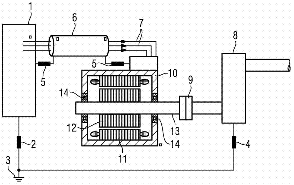
[0111] figure 1 Shows a schematic diagram of the construction of a motor with peripheral equipment components. It is shown in detail here that the converter 1 is connected to the electric motor by a connecting line 7. The electric motor is located in the motor housing 10 and has a stator 11 and a rotor 12, which drives a load through a coupling 9 through a bearing 14 and a shaft 13 The machine 8 is either driven by the load machine.

[0112] The electrical connection between the converter 1 and the motor through the connecting cable 7 has a cable shield 6 which has a corresponding connection 5 with the ground wire of the converter or the motor housing. Both the converter 1 and the load machine 8 are connected to the ground 3 through the ground 2 or 4. The motor can also be connected to the ground, which of course is not shown in the figure. The electric motor may have two grounding points, for example. A grounding point is located, for example, in the area of ​​the foot of the...


PUM


Abstract

In a system for ascertaining a bearing state and in a method for ascertaining a bearing state of a bearing of an electric machine, a measurement value (21) is ascertained by means of a sensor unit (20). The measurement value is transmitted to a simulation unit (22), wherein a result value (23) is ascertained by means of the simulation unit (22), wherein the result value is in particular a bearing-current value or a value that is dependent on the bearing current. The result value (23) can be transmitted to a further unit (24).

Description

Technical field [0001] The present invention relates to a method and a device / system for simulating the electric bearing load of a bearing of a motor. Background technique [0002] In the bearings of electric machines, such as generators or electric motors, undesirable currents may be generated as a consequence of electrostatic charging or when feeding power with the aid of high-power electronic regulating components. For these bearing currents, it is partly referred to as the so-called EDM (Electric Discharge Machining)-current, in which arc discharge occurs in the bearing. In particular, arcing and discharge occur in the lubricating film between the rolling elements and raceways of the respective bearings. Therefore, in general, premature wear of the lubricating medium and bearings may occur. Premature failure of the bearing is also a possible consequence. Summary of the invention [0003] The purpose of the present invention is to propose a method and a device for simulating...

Claims


Application Information

Patent Timeline
Patent Type & Authority Applications(China)
IPC IPC(8): G01M13/04
CPCG01M13/04
Inventor 托马斯·弗鲁约尔格·哈塞尔卡斯滕·普罗博尔汉斯·蒂施曼彻
Owner SIEMENS AG
Why Eureka
Try Eureka