
Reflective solar concentrator without optical equalizing rod

A concentrator and concentrating light technology, which is applied in the field of solar concentrators, can solve the problems of increased current impedance, increased light consumption, and reduced power generation efficiency, and achieves the effects of uniform illumination, high power generation efficiency, and low cost

Inactive Publication Date: 2012-11-07
姜莹
View PDF6 Cites 3 Cited by
  • Summary
  • Abstract
  • Description
  • Claims
  • Application Information

AI Technical Summary

Problems solved by technology

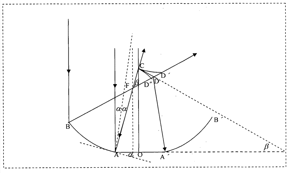
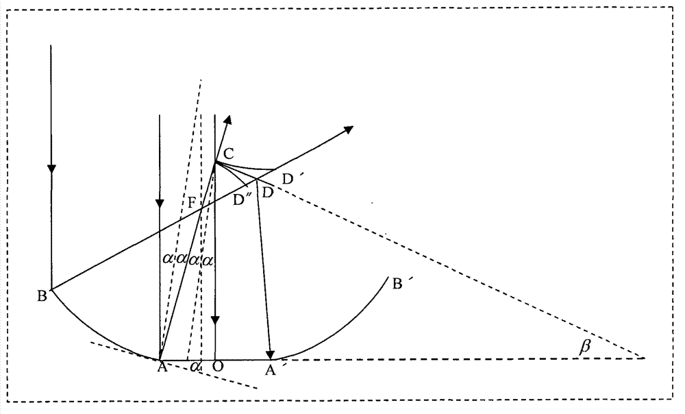
[0004] exist figure 1 In the design, due to the blocking of the direct sunlight 3 by the secondary reflector 2 itself, the light spot of the secondary reflection will leave a blind area on the light-gathering surface. Such a design is generally used for high-magnification light-gathering, but there is a large Design flaws, in order to reduce the blind area, in many designs, a uniform light rod is added between the secondary reflector and the light-condensing surface, which not only increases the cost, but also increases the light consumption. In addition, strictly speaking, the blind area still can not be completely eliminated
[0005] Using the rotating paraboloid described in traditional optics as a reflector, no matter how the size of the reflective surface is changed, the focal length or the focus position is changed, the light reflected by the secondary reflector cannot be covered in a complete and uniform manner without blind spots. On the surface, such spot distribution is unfavorable for photovoltaic power generation, because we know that non-uniform illumination will reduce the filling factor of photovoltaic cells and increase the current impedance, thereby greatly reducing power generation efficiency

Method used


Image

  • Reflective solar concentrator without optical equalizing rod
  • Reflective solar concentrator without optical equalizing rod
  • Reflective solar concentrator without optical equalizing rod

Examples


Embodiment Construction

[0037] specific implementation

[0038] In the study of the reflective concentrator, since the reflective parabola can be a paraboloid of revolution formed by the parabola rotating around the central axis or a parabolic cylinder formed by the parabola extending along the axis perpendicular to the plane of the parabola, in order to simplify the problem, we can first In-dimensional research. like figure 1 In , both the primary reflector and the secondary reflector can be simplified as parabola segments. The primary reflector can be a paraboloid of revolution formed by rotating the parabola segment AB and its symmetric line segment relative to the central axis together around the central axis or a parabolic cylinder extending along an axis perpendicular to the plane. The secondary reflector can be formed by the parabola segment CD is a paraboloid of revolution formed by rotating around the central axis together with its symmetric line segment relative to the central axis, or a ...


PUM


Abstract

The invention relates to a reflective solar concentrator without an optical equalizing rod, which comprises a primary reflector and a secondary reflector, wherein the primary reflector is used for condensing light and is provided with a hole in the centre, the hole is used for installing a photoelectric device to form a condensation surface; the secondary reflector is used for reflecting reflective ray of the primary reflector, the concentrator has a central symmetric axis, the primary reflector is a revolution paraboloid formed in such a manner that a parabolic segment whose focus is not on the central axis, and another segment which is symmetric to the parabolic segment respective to the central axis revolve around the central axis or extend along the axis which is perpendicular to the segment plane, the secondary reflector is a rotation surface or a cylindrical surface which is formed a line segment of which the starting points are on the central axis, and another line segment symmetric with the line segment relative to the central axis by the way of rotating around the central axis or extending along the axis which is perpendicular to the segment plane, the incident rays parallelly irradiating on the primary reflector uniformly irradiate on the condensation surface through the primary reflector and the secondary reflector without a blind area. The concentrator can be used for high-power solar concentration without the optical equalizing rod and has the advantages of no blind area, uniform illumination, low cost and high generating efficiency.

Description

technical field [0001] The invention relates to a light concentrating part in a solar photovoltaic device, in particular to a low-cost and high-efficiency solar concentrator without reflection of a uniform light bar. Background technique [0002] Highly efficient use of solar energy for photovoltaic power generation is a major issue to solve the world's energy problems. Since solar energy is a low-density energy, high-power concentration is one of the methods to improve the quality factor of solar energy. Solar concentrators for photovoltaic power generation generally must place photovoltaic devices below to receive solar light from above. The general structure of the above-mentioned concentrator is: the primary concentrator (generally using a rotating paraboloid or parabolic cylinder) is placed below, and the secondary reflector reflects the light reflected to the top to the bottom for the installation of photoelectric devices. face. Since the concentrators in question ar...

Claims


Application Information

Patent Timeline
IPC IPC(8): G02B19/00G02B5/10G02B7/182H02N6/00H02S40/22
CPCY02E10/52
Inventor 吴松江
Owner 姜莹
Learn More