
Building wall apparent heat transfer coefficient field detection method suitable for districts hot in summer and warm in winter

A heat transfer coefficient and on-site detection technology, applied in the direction of material thermal conductivity, material thermal development, etc., can solve problems such as unsuitable heat transfer coefficient measurement, achieve good environmental condition adaptability, shorten test time, and wide-ranging effects

Active Publication Date: 2012-10-31
CHINA ACADEMY OF BUILDING RES TIANJIN INST
View PDF6 Cites 24 Cited by
  • Summary
  • Abstract
  • Description
  • Claims
  • Application Information

AI Technical Summary

Problems solved by technology

Fifth, in the detection method proposed by this patent, the actual thickness of the wall to be measured, the measurement area and the surrounding windows, doors, beams, columns, ceilings and floors are not involved in the data processing and calculation of the wall heat transfer coefficient value. distance size
Therefore, this patent should not be applied to the measurement of heat transfer coefficient of walls near doors and windows (such as under windows) during on-site testing

Method used


Image

  • Building wall apparent heat transfer coefficient field detection method suitable for districts hot in summer and warm in winter
  • Building wall apparent heat transfer coefficient field detection method suitable for districts hot in summer and warm in winter
  • Building wall apparent heat transfer coefficient field detection method suitable for districts hot in summer and warm in winter

Examples


Embodiment Construction

[0023] Below in conjunction with accompanying drawing and embodiment the technical scheme of the present invention will be further described:

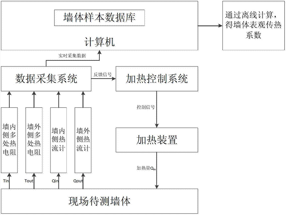
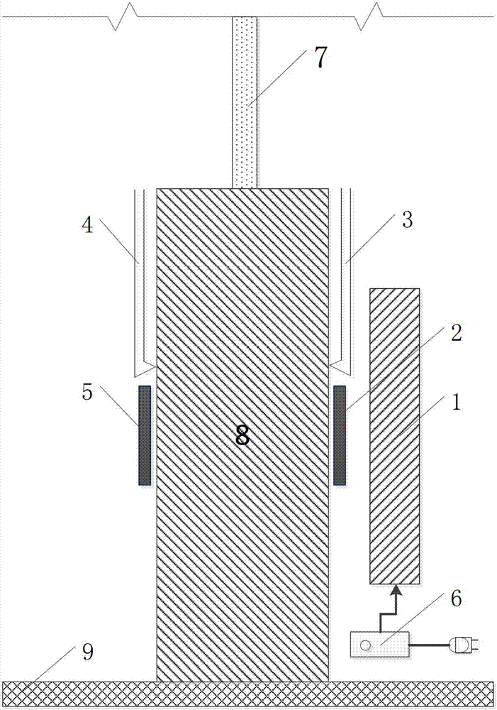
[0024] refer to figure 1 The first step of implementing the on-site detection method for the apparent heat transfer coefficient of building walls suitable for hot summer and warm winter regions according to the present invention is to arrange detection devices. At the testing site, first select a suitable wall to be tested. like image 3 As shown, the wall 8 (the bottom is connected to the floor 9) at the lower part of the form 7 of a certain building exterior wall can be selected as the object wall. Appropriate parts of the inner and outer surfaces of the object wall (preferably the geometric center of the object wall surface) are taken as the measurement area. Then start to arrange the thermal resistance, heat flow meter and heating device required for measurement. First paste the heat flow meter board 2 on the inner surface of the...


PUM


Abstract

The invention discloses a novel heating device of an apparent heat transfer coefficient field detection system for a wall body enclosure structure. The novel heating device mainly comprises a heat homogenizing plate, a flexible electric heating coil layer, an outer heat-isolation material layer, an inner heat-isolation material layer, an electric power adjuster and the like, wherein the heat homogenizing plate is tightly pressed against the surface of a wall body to be detected and can be used for uniformly heating the wall body. The periphery of the heat homogenizing plate is provided with the inner heat-isolation material layer which is located between a wall face and the heat homogenizing plate. The flexible electric heating coil layer is arranged on the back face of the heat homogenizing plate. The external heat-isolation material layer is arranged on the back face of the flexible electric heating coil layer so as to prevent the heat produced by the heating coil from being lost at the back of the coil in an isolation manner. The novel heating device is suitable for heating in the field detection of the apparent heat transfer coefficient of the wall body enclosure structure, is light in total weight, easy to regulate in electric heating power, rapid to assemble and disassemble and suitable for carrying, and the number of the heat homogenizing plates can be increased or decreased according to the actual dimension of the wall body in a detection field.

Description

technical field [0001] The invention relates to building detection, in particular to an on-site detection method for the apparent heat transfer coefficient of building walls in hot summer and warm winter regions. Background technique [0002] The energy consumption of various buildings is an important aspect of the total energy consumption. In order to promote building energy-saving technology, the detection of building maintenance structure is an important content. The state and local governments have promulgated a series of building energy-saving testing standards, such as "Heating Residential Building Energy Saving Testing Standard" (JGJ132-2001), Beijing "Civil Building Energy Conservation Site Inspection Standard" and Shanghai "Residential Building Energy Conservation Testing and Evaluation Standard", etc. . Among them, the detection of heat transfer coefficient of building maintenance structure is an important index. [0003] The definition of the apparent heat tran...

Claims


Application Information

Patent Timeline
IPC IPC(8): G01N25/20
CPCG01N25/20G01N25/18
Inventor 尹波周海珠胡佳僖杨彩霞王雯翡魏慧娇闫静静惠超微张蕊
Owner CHINA ACADEMY OF BUILDING RES TIANJIN INST
Learn More