
Device for measuring density of cryogenic fluid

A low-temperature fluid density and measuring device technology, applied to measuring devices, specific gravity measurement, instruments, etc., can solve the problems of complex structure, limited temperature and pressure range, high requirements for liquid oxygen sampling, etc., to achieve convenient operation and reliable Effects with strong repeatability and simple structure

Inactive Publication Date: 2014-03-26
SHANGHAI JIAO TONG UNIV
View PDF5 Cites 0 Cited by
  • Summary
  • Abstract
  • Description
  • Claims
  • Application Information

AI Technical Summary

Problems solved by technology

The device is only suitable for temperature 90~100K, pressure 0.1MPa~0.6MPa, and the structure is relatively complex, and the requirements for liquid oxygen sampling are high
The invention patent with the authorization number CN1664553A and the invention patent with the application publication number of CN102428357A both disclose an experimental device for measuring fluid density by vibration method, and the invention patent with the application publication number of CN102288516A discloses a method for simultaneously measuring fluid density, pressure and temperature based on MEMS technology. Integrated fluid sensors, most of these inventions are limited to a small range of temperature and pressure, which cannot meet the needs of measuring the density of cryogenic fluids

Method used


Image

  • Device for measuring density of cryogenic fluid
  • Device for measuring density of cryogenic fluid
  • Device for measuring density of cryogenic fluid

Examples


Embodiment Construction

[0022] The conception, specific structure and technical effects of the present invention will be further described below in conjunction with the accompanying drawings, so as to fully understand the purpose and characteristics of the present invention.

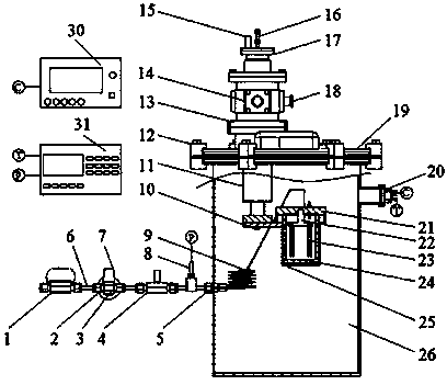
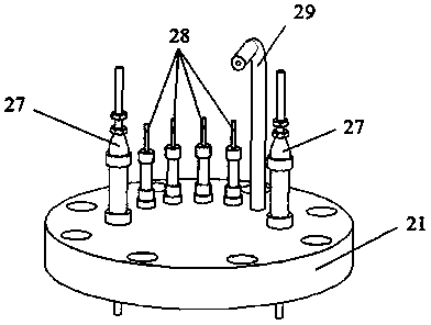
[0023] see first figure 1 and figure 2 , figure 1 It is a structural schematic diagram of an embodiment of the cryogenic fluid density measuring device of the present invention, figure 2 It is a structural schematic diagram of the embodiment of the flange cover of the sample bottle. As can be seen from the figure, the cryogenic fluid density measuring device of the present invention comprises a gas charging and discharging gas connection pipeline, a vacuum housing 26 and a vacuum housing flange 19, a sample bottle 24 and a sample bottle flange cover 21, a capacitive density sensor 23, a guide Cold base 25, temperature measurement and control system and pressure measurement system:

[0024] The charging and discharging gas...


PUM


Abstract

The invention relates to a device for measuring the density of cryogenic fluid by a dielectric constant method. The device comprises a charging and discharging gas connecting pipeline, an outer vacuum cover, an outer vacuum cover flange, a sample bottle, a sample bottle flange cover, a capacitance-type density sensor, a cold guide base, a temperature measuring and controlling system and a pressure measuring system. A gas pipeline is respectively connected with an air source steel cylinder, a vacuum pump and the sample bottle by a tee joint; the capacitance-type density sensor is movably connected with the sample bottle flange cover by a support structure; capacitance data are collected by a high-precision inductance-capacitance-resistance (LCR) digital electric bridge; and the sample bottle is arranged in the cold guide base which is in threaded connection with a cold head of a liquid nitrogen thermostat. The measuring device has a simple structure, is strong in repeatability and convenient to operate and can accurately measure the density of a single phase and a two-phase mixture of the pure fluid within 80K-310K and 0.1MPa-8MPa.

Description

technical field [0001] The invention relates to low-temperature fluid density measurement, in particular to a low-temperature fluid density measurement device using a dielectric constant method. Background technique [0002] Accurate low temperature fluid thermodynamic properties data is indispensable for scientific research and engineering design. In the fields of aerospace, liquefied natural gas, low-temperature superconductivity, and air separation, there are a large number of demands for high-precision measurement of cryogenic fluid density, and some even require online real-time measurement. Sufficient and accurate experimental data is a necessary prerequisite for the development of empirical or semi-empirical equations of state, and precise density measurement devices are of great significance for revealing the internal laws of thermodynamic properties of new fluids and describing the state of existence of substances. [0003] There are two methods for measuring the d...

Claims


Application Information

Patent Timeline
Patent Type & Authority Patents(China)
IPC IPC(8): G01N9/00
Inventor 黄永华于琦翁捷敏
Owner SHANGHAI JIAO TONG UNIV
Learn More