Multi-stage pressure-reduction water saving valve
A technology of water saving valve and water inlet valve, which is applied in the direction of lift valve, valve details, valve device, etc., can solve the problems of difficult to guarantee water demand, insufficient safety, large water flow rate, etc., and achieve huge economy. Value and social value, avoidance of splashes, effect of reduced water flow velocity
- Summary
- Abstract
- Description
- Claims
- Application Information
AI Technical Summary
Problems solved by technology
Method used
Image
Examples
Embodiment 1
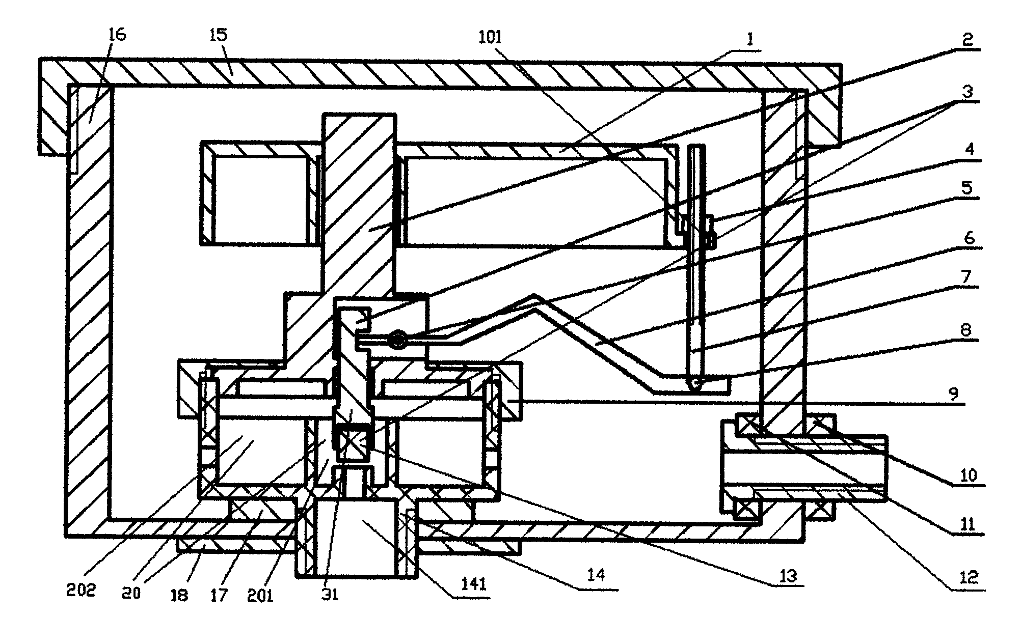
[0044] A multi-stage decompression and water-saving valve; refer to figure 1 ; It is mainly composed of the following structures: float 1, water inlet valve seat, water saving valve body 16; wherein:
[0045] The water-saving valve body 16 is a structure with a cavity for water storage inside, and an opening is provided at the lower part; specifically, there are two openings: a water inlet and a water outlet;
[0046] The float 1 is arranged on the upper part of the inner cavity of the water saving valve body 16;
[0047] The water inlet valve seat is specifically composed of the water inlet valve upper seat 2, the water inlet valve lower seat 14 and the water inlet valve core seat 3, wherein: the water inlet valve upper seat 2 and the water inlet valve lower seat 14 are arranged in a fixed connection with each other In the lower part of the inner cavity of the water saving valve body 16, the upper seat 2 of the water inlet valve and the lower seat 14 of the water inlet valve...
Embodiment 2
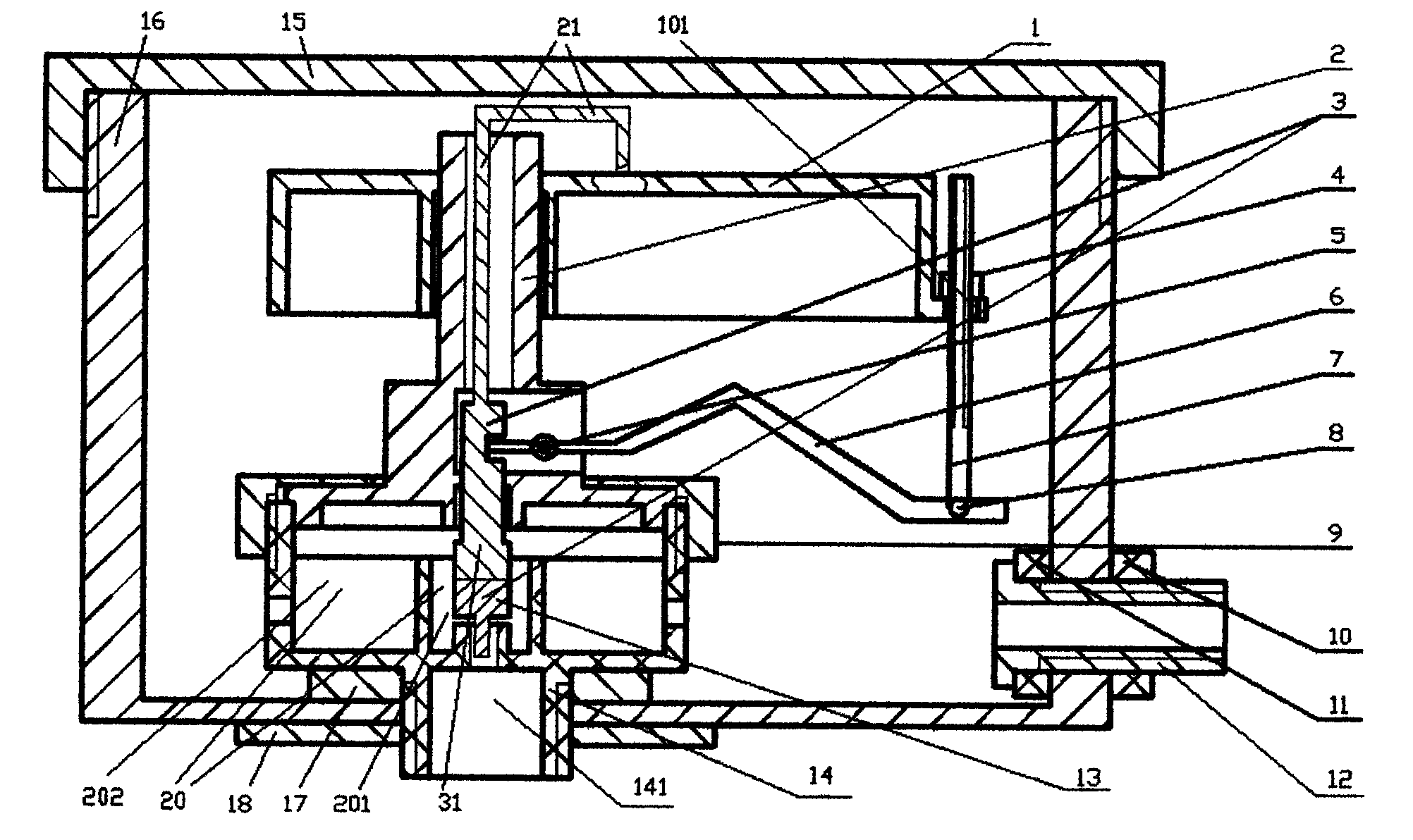
[0076] The content of this embodiment is basically the same as that of Embodiment 1 (refer to figure 2 ), the main differences are:
[0077] 1) The multi-stage decompression and water-saving valve is provided with a structure for controlling the height position of the water inlet valve core seat 3 in the vertical direction according to the position of the float 1, which meets the following requirements:
[0078] The multi-stage decompression and water-saving valve is provided with a structure for controlling the height position of the water inlet valve core seat 3 in the vertical direction according to the position of the float 1, which meets the following requirements: The connecting rod 21 fixedly connected with the valve core seat 3 of the water inlet valve and the float 1 is also arranged in the water-saving valve of the stage decompression. Simultaneously perform up and down movements.
[0079] 2) In the multi-stage decompression and water-saving valve, the inner cavit...
Embodiment 3
[0091] This embodiment is basically the same as embodiment 1 or 2 (do not provide figure, but can refer to figure 1 Or 2 corresponds to understanding), the difference mainly lies in:
[0092] 1) The water inlet valve inner chamber 20 inside the water inlet valve upper seat 2 and the water inlet valve lower seat 14 communicates with the inner cavity of the water saving valve body 16 through one of the following structures or a combination thereof: a hole with a circular cross section , flow channels and slits with non-circular cross-sections;
[0093] 2) When this embodiment is based on Embodiment 1, the multi-stage decompression and water-saving valve also meets the following requirements: the multi-stage decompression and water-saving valve is provided with a control valve that meets the following requirements According to the position of the float 1, the structure of adjusting the height position of the valve core seat 3 of the water inlet valve in the vertical direction is...
PUM
 Abstract
Description
Claims
Application Information
 - R&D
- Intellectual Property
- Life Sciences
- Materials
- Tech Scout
- Unparalleled Data Quality
- Higher Quality Content
- 60% Fewer Hallucinations
Browse by: Latest US Patents, China's latest patents, Technical Efficacy Thesaurus, Application Domain, Technology Topic, Popular Technical Reports.
© 2025 PatSnap. All rights reserved.Legal|Privacy policy|Modern Slavery Act Transparency Statement|Sitemap|About US| Contact US: help@patsnap.com


