Sintered magnet and method for producing the same

A technology of sintered magnets and magnets, applied in the manufacture of inductors/transformers/magnets, motor generators, and stator/rotor bodies, etc., can solve the problems of scarcity, high cost, and high manufacturing costs of permanent magnets, and reduce eddy current loss. , the effect of rich shape changes

Inactive Publication Date: 2012-10-24
TOYOTA JIDOSHA KK
View PDF6 Cites 6 Cited by
  • Summary
  • Abstract
  • Description
  • Claims
  • Application Information

AI Technical Summary

Problems solved by technology

This rare earth magnet increases its coercive force by adding elements dysprosium (Dy) and terbium (Tb) with high crystal magnetic anisotropy. On the other hand, these elements are rare and expensive, and are added to increase the coercive force of permanent magnets. Dysprosium, etc. directly lead to high manufacturing costs of permanent magnets
[0009] However, in the permanent magnets used in the rotors of conventional magnet-embedded motors, dysprosium or the like for obtaining the above-mentioned coercive force required at the corners is used for the entire permanent magnets, so the rotor manufacturing cost is high.
Furthermore, the residual magnetic flux density, which is as important as the coercive force as the performance of the permanent magnet, tends to decrease as the coercive force increases. Therefore, in order to solve the decrease in the magnetic flux density due to the increase in the coercive force, Requires more magnets and thus makes the rotor more expensive to manufacture

Method used


Image

  • Sintered magnet and method for producing the same
  • Sintered magnet and method for producing the same
  • Sintered magnet and method for producing the same

Examples


Embodiment Construction

[0046] Hereinafter, embodiments of the present invention will be described with reference to the drawings. It should be noted that, of course, the shape of the sintered magnet assembled from the basic magnets is not limited to the illustrated example.

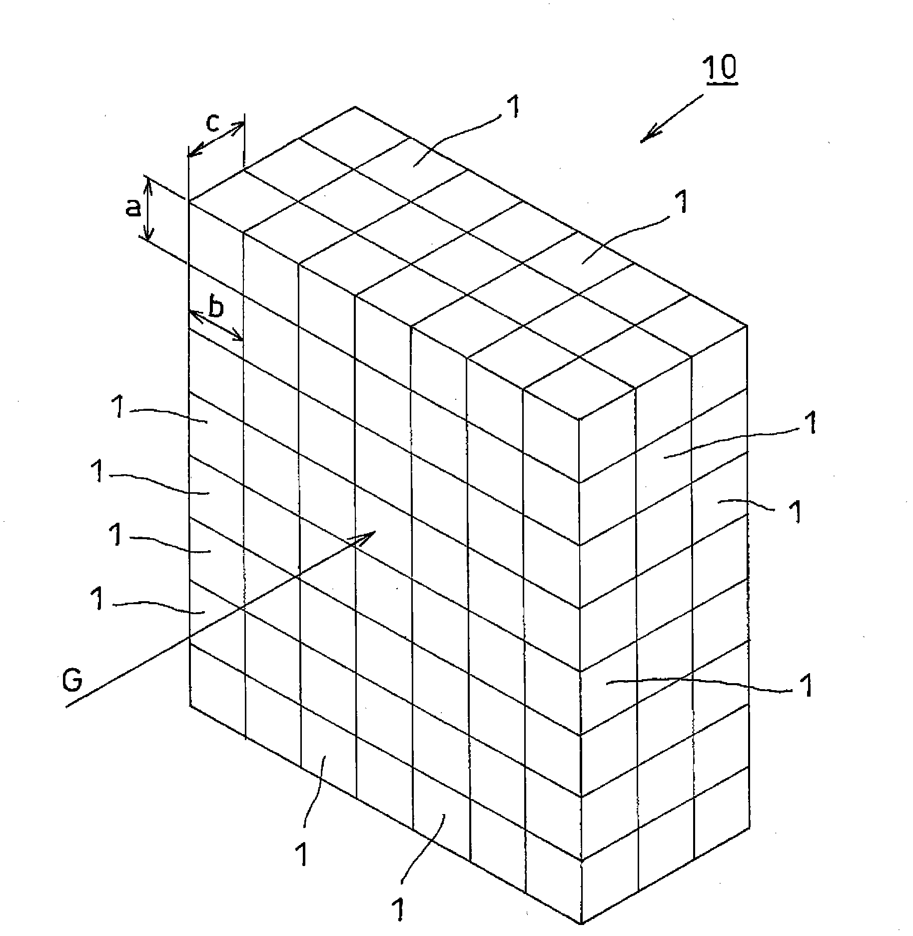
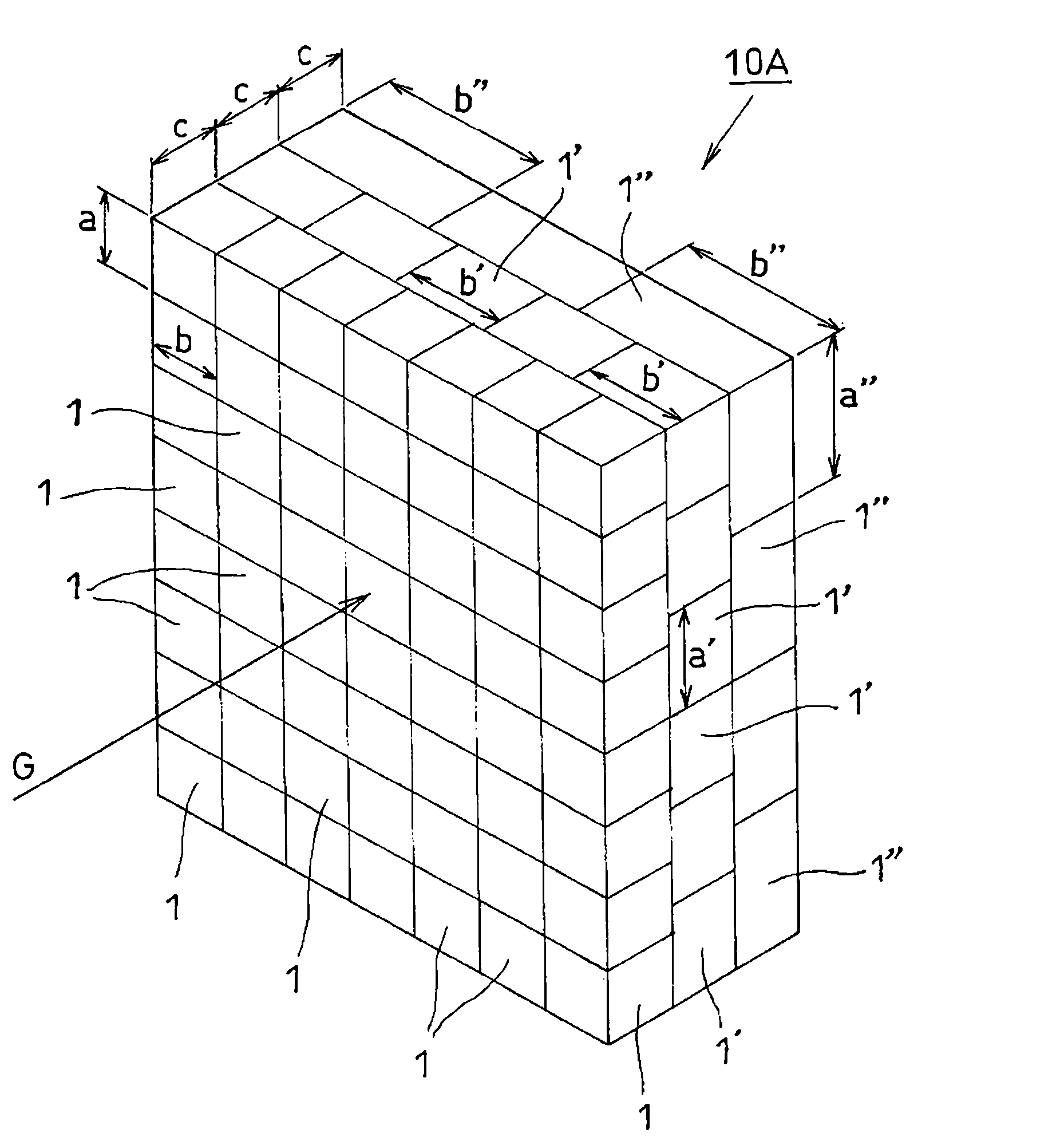
[0047] figure 1 , 3 , 4, and 5 are perspective views illustrating an embodiment of a sintered magnet, respectively.

[0048] first, figure 1 The shown sintered magnet 10 is formed from a single basic magnet of the same shape, the length of the longitudinal side: a, the length of the transverse side: b, and the height: c are all cube-shaped basic magnets 1 of the same size in the longitudinal, transverse and height directions A plurality of each is provided in parallel, and the basic magnets 1 and 1 are joined with each other only by the magnetic force they have.

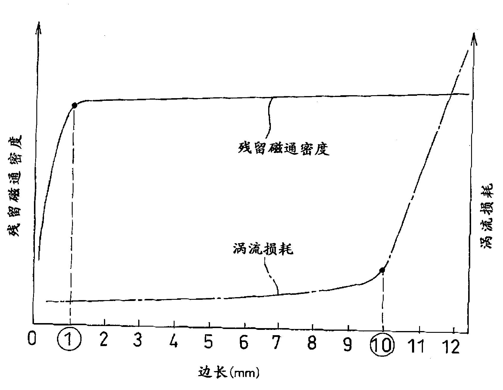
[0049] Here, the side lengths of the basic magnet 1: the lengths of a, b, and c are set within a range of 1 mm to 10 mm. refer to figure 2 The basis for sett...


PUM

PropertyMeasurementUnit
lengthaaaaaaaaaa

Abstract

Provided are a sintered magnet capable of reducing eddy-current loss markedly as compared with a conventional split magnet, accommodating a variety of shapes and dimension variation and reducing the manufacturing cost markedly while having a desired coercive force, and a method for producing the sintered magnet. A sintered magnet (10) is a rectangular parallelepiped or a cube having the length of one side in the range of 1-10 mm, wherein a single base magnet (1) of the same shape or a plurality of base magnets (1,...) having different shapes are arranged, respectively, in the longitudinal and lateral directions forming a plane and in the height direction intersecting the plane perpendicularly, and junction between the base magnets (1, 1) is maintained by the magnetic force of at least adjoining base magnets (1, 1).

Description

technical field [0001] The present invention relates to a sintered magnet embedded in, for example, a rotor constituting a magnet-embedded motor, and a method of manufacturing the same. Background technique [0002] The magnet embedded motor (IPM motor) in which the permanent magnet is embedded in the rotor can obtain the reluctance torque in addition to the magnetic torque caused by the attractive / repulsive force of the coil and the permanent magnet. The surface magnet type motor (SPM motor) formed on the outer peripheral surface of the rotor has high torque and high efficiency. Therefore, this magnet-embedded motor is used in drive motors of hybrid vehicles and electric vehicles, etc., which require high output performance. [0003] In addition, coils are formed by winding wires intensively or distributed on the stator teeth, and magnetic flux is generated by passing current through the coils, and magnetic torque and reluctance torque are generated between the magnetic fl...

Claims


Application Information

Patent Timeline
Patent Type & Authority Applications(China)
IPC IPC(8): H02K15/03H02K1/27
CPCH02K1/276H01F41/0266H01F7/0205H02K15/03H02K1/27H01F1/086Y10T29/49012
Inventor 金田敬右
Owner TOYOTA JIDOSHA KK
Why Eureka
Try Eureka