Floating type water nozzle

A floating and faucet technology, applied in valve lifts, shaft seals, valve details, etc., can solve the problems of seal leakage, waste of water resources and economic losses, insurmountable valve seat sealing performance, etc., to reduce manufacturing costs, The effect of prolonging the service life and improving the sealing performance

Inactive Publication Date: 2012-10-24
HUBEI GOLDEN ARROW VALVE CO LTD
View PDF6 Cites 2 Cited by
  • Summary
  • Abstract
  • Description
  • Claims
  • Application Information

AI Technical Summary

Problems solved by technology

Therefore, its upper seal design has congenital deficiencies and is not accepted by the majority of users.
[0004] 2. At the end of the 1990s, my country developed a "ceramic seal faucet", which effectively solved the problem of seal leakage on the "screw lift faucet". There are still insurmountable disadvantages in the sealing performance of the valve seat in the valve body
Whether it is "outside leakage" or "inside leakage", it brings great troubles to people's life and spirit, and a lot of waste of very precious water resources and economic losses

Method used


Image

  • Floating type water nozzle
  • Floating type water nozzle
  • Floating type water nozzle

Examples


Embodiment Construction

[0022] The following is a detailed description of the specific implementation of the new floating cold water nozzle according to the accompanying drawings:

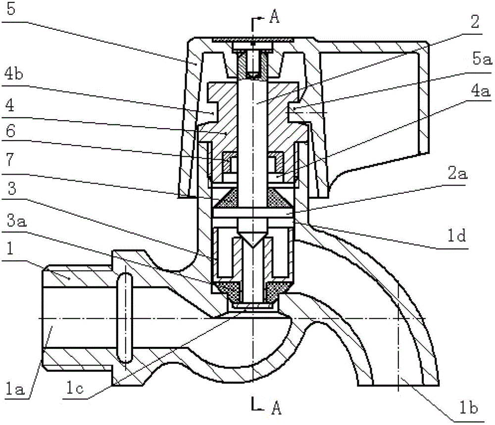
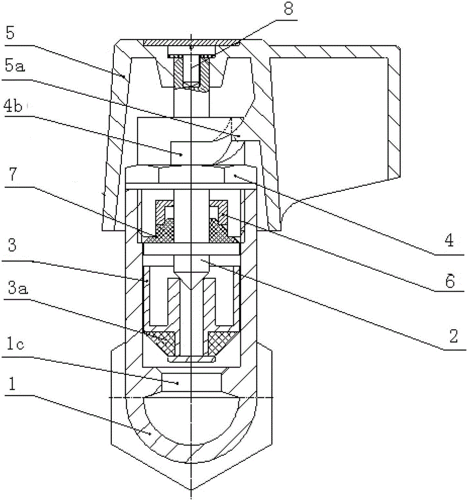
[0023] figure 1 , figure 2 A floating faucet of the present invention is given, including a valve body 1, a valve stem 2, a valve core assembly 3, a valve cover 4, and a handle cover 5. The valve body 1 includes a water inlet 1a, a water outlet 1b, and a valve cavity 1d , the switch control port 1c between the water inlet 1a and the water outlet 1b is at the bottom of the valve chamber 1d, the valve core assembly 3 includes a floating plug 3a, and the floating plug 3a is placed at the bottom of the valve chamber 1d in the valve body 1, and the valve chamber 1d There is a gap fit, the upper part of the floating plug 3a has a central blind hole coaxial with the valve stem 2, the lower part of the floating plug 3a is installed with a conical lower gasket 3b, and the conical lower gasket 3b corresponds to the switch control...


PUM


Abstract

The invention provides a floating type water nozzle which comprises a valve body, a valve rod, a valve core assembly, a valve cover and a hand shank cover, wherein the valve body comprises a water inlet, a water outlet and a valve cavity; a switch control port is formed at the bottom of the valve cavity; the valve core assembly comprises a floating plug; the floating plug is arranged at the bottom of the valve cavity in the valve body and is in clearance fit with the valve cavity; a central blind hole is formed on the upper part of the floating plug and is coaxial with the valve rod; a conical lower sealing pad is arranged on the lower part of the floating plug and corresponds to the switch control port on the lower part of the valve cavity; the valve cover is in threaded connection to anupper opening of the valve cavity; a sealing concave pit is formed on the lower part of the valve cover; a threaded guide slot is formed on the outer cylinder on the upper part of the valve cover; the upper end of the valve rod is fixed on the top of the hand shank cover; the middle part of the valve rod passes through a central hole of the valve cover; the conical end on the lower part of the valve rod is aligned with the central blind hole on the upper part of the floating plug; a disk is arranged on the lower part of the valve rod; a conical upper sealing pad is arranged on the disk and corresponds to the sealing concave pit on the lower part of the valve cover; and a convex column in the inner cavity of the hand shank cover and the threaded guide slot on the outer cylinder on the upper part of the valve cover form an execution mechanism.

Description

technical field [0001] The invention relates to a floating faucet, which is an energy-saving, safe and clean faucet used for the opening and closing of pipeline medium terminals, and belongs to the technical field of pipeline valves. It is mainly used in the daily water supply business, which can effectively solve the problem of poor sealing performance of the traditional cold water nozzle. Background technique [0002] The cold water spout is derived from the pipeline valve (commonly known as "faucet"). There are many styles at home and abroad, but in terms of internal opening and closing structure and sealing form, there are currently only two types. Spiral lifting faucet", one is the "ceramic sheet sealing faucet" produced in the late 1990s. The functional structures of these two faucets have their own advantages and disadvantages, but in terms of their sealing performance, they have not completely solved this problem. Even The theoretical service life has not been well ...

Claims


Application Information

Patent Timeline
Patent Type & Authority Applications(China)
IPC IPC(8): F16K1/00F16K31/50F16K31/60F16K27/12F16K41/04
Inventor 黎光新
Owner HUBEI GOLDEN ARROW VALVE CO LTD
Why Eureka
Try Eureka