Follow-up drilling machine for sleeve of down-the-hole hammer

A technology of down-the-hole hammer and casing, applied in casing, drill pipe, drill pipe, etc., can solve the problems of uneven force on the column, difficult to separate, increase the weight of one side of the column, etc., so as to save production costs and equipment. The effect of low cost and simple structure

Inactive Publication Date: 2012-10-24
威海市海泰起重机械有限公司
View PDF2 Cites 10 Cited by
  • Summary
  • Abstract
  • Description
  • Claims
  • Application Information

AI Technical Summary

Problems solved by technology

However, the above-mentioned dual-drive casing drilling rig technology has the following disadvantages: Since the outer casing and the drill pipe are driven by the top of the power head, the casing and the power head are not easy to separate and must be pulled out of the ground at the same time as the drilling tool, and the long helical drill hole is directly poured. It’s okay, but it’s hard to guarantee the quality of reinforcement cages and cast-in-place construction piles under rock construction with down-the-hole hammers
The power head of the casing drilling rig can not only drive the drilling tool at the top, but also drive it at the middle or lower part of the drilling tool. The height of the power head of the drilling rig relative to the ground can be lowered by more than 1 / 2 compared with the top drive. The disadvantages are: 1. . Since the pulley block on the top of the column adopts the multiplier type pulley, and the side of the column adopts double drive power heads, which not only increases the weight of one side of the column, but also makes the force on the front and rear of the column uneven, resulting in a larger bending moment of the column and increasing the The weight of the top pulley block greatly reduces the stability of the pile driver

Method used


Image

  • Follow-up drilling machine for sleeve of down-the-hole hammer
  • Follow-up drilling machine for sleeve of down-the-hole hammer
  • Follow-up drilling machine for sleeve of down-the-hole hammer

Examples


Embodiment Construction

[0021] Below in conjunction with accompanying drawing, the present invention is further described:

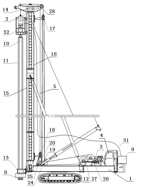
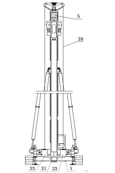
[0022] As shown in the drawings, a DTH hammer casing follow-up drilling rig includes a support machine, an impact device, a vibratory hammer, a drill pipe 10 and a casing 11, and the support machine includes a base 1, a column 2, a hoist 3, and an operating room 4 And steel wire rope 5,28, impact device comprises down-the-hole hammer 8 and air compressor 9, and the structure of down-the-hole hammer 8 is identical with prior art, this does not go into details, drill pipe 10 outside is sleeved with sleeve pipe 11, and base 1 lower end can adopt Crawler-type traveling device 12 or walking device 12, crawler-type traveling device 12 or walking device 12 are prior art, this does not go into details, base 1 upper end is provided with winch 3 and operating room 4, and base 1 front end is provided with column 2, The lower part of casing 11 is provided with casing 13, and casing 13 is f...


PUM


Abstract

The invention relates to the technical field of engineering pile machines, in particular to a follow-up drilling machine for a sleeve of a down-the-hole hammer. The follow-up drilling machine for the sleeve of the down-the-hole hammer comprises a supporting machine, an impact device, a vibrating hammer, a drill stem and the sleeve, wherein the supporting machine comprises a base, an upright post, a winding engine, an operating room and a towing steel rope; the impact device comprises the down-the-hole hammer and an air compressor; the sleeve is sleeved outside the drill stem; a top pulley block is arranged at the upper end of the upright post; and guide slide rails are arranged at two sides of the upright post. The follow-up drilling machine for the sleeve of the down-the-hole hammer is characterized in that a power head is arranged on the guide slide rail at the front side of the upright post; a movable pulley block I and a movable pulley block II are arranged on the guide slide rail at the rear side of the upright post; a fixed pulley block I and a fixed pulley block II are arranged on the base; a beam is arranged at the lower part of the sleeve in front of the base, and the drill stem is a bladeless steel tube. The structure is adopted, so that the follow-up drilling machine for the sleeve of the down-the-hole hammer has the advantages of simple structure, low center of gravity, high stability, low device cost and the like.

Description

technical field [0001] The invention relates to the technical field of engineering pile machines, in particular to a down-the-hole hammer casing follow-up drilling rig. Background technique [0002] At present, in order to solve the problem that the long auger drilling rig is difficult to enter the rock, and prevent the hole wall from collapsing during the construction of the bored pile, which will cause the stuck drill and affect the quality of the pile body; the mud retaining wall will cause problems such as increased cost and environmental pollution; One is to use the casing to follow up the equipment and construction technology of the retaining wall to form holes. There are three main methods for the casing to follow up: 1. The immersed pipe method, the casing is sunk into the ground by hammering, vibration or static pressure; 2. Shaking the pipe 3. Rotating pipe method, the casing is drilled into the ground by static pressure or gravity while rotating. The above three ...

Claims


Application Information

Patent Timeline
Patent Type & Authority Applications(China)
IPC IPC(8): E21B4/16E21B17/00
Inventor 于建池曹少东
Owner 威海市海泰起重机械有限公司
Why Eureka
Try Eureka