
Watt connecting rod installation structure

A technology of installation structure and watt connecting rod, which is applied in the directions of interconnection system, transportation and packaging, suspension, etc., can solve the problems of insufficiently compact bottom structure, high longitudinal space, difficult application, etc., to achieve compact structure, improve stability, Strong connection

Pending Publication Date: 2018-08-17
马瑞利汽车零部件(广州)有限公司
View PDF0 Cites 1 Cited by
  • Summary
  • Abstract
  • Description
  • Claims
  • Application Information

AI Technical Summary

Problems solved by technology

[0004] However, due to the arrangement of the Watt connecting rod, a large longitudinal space needs to be reserved at the bottom of the car, which makes the bottom structure of the car not compact enough, which runs counter to the expectations and requirements of market consumers.
Also because the Watt connecting rod has high requirements on the longitudinal space at the bottom of the car, it is difficult to apply it to models with a low chassis

Method used


Image

  • Watt connecting rod installation structure
  • Watt connecting rod installation structure

Examples


Embodiment Construction

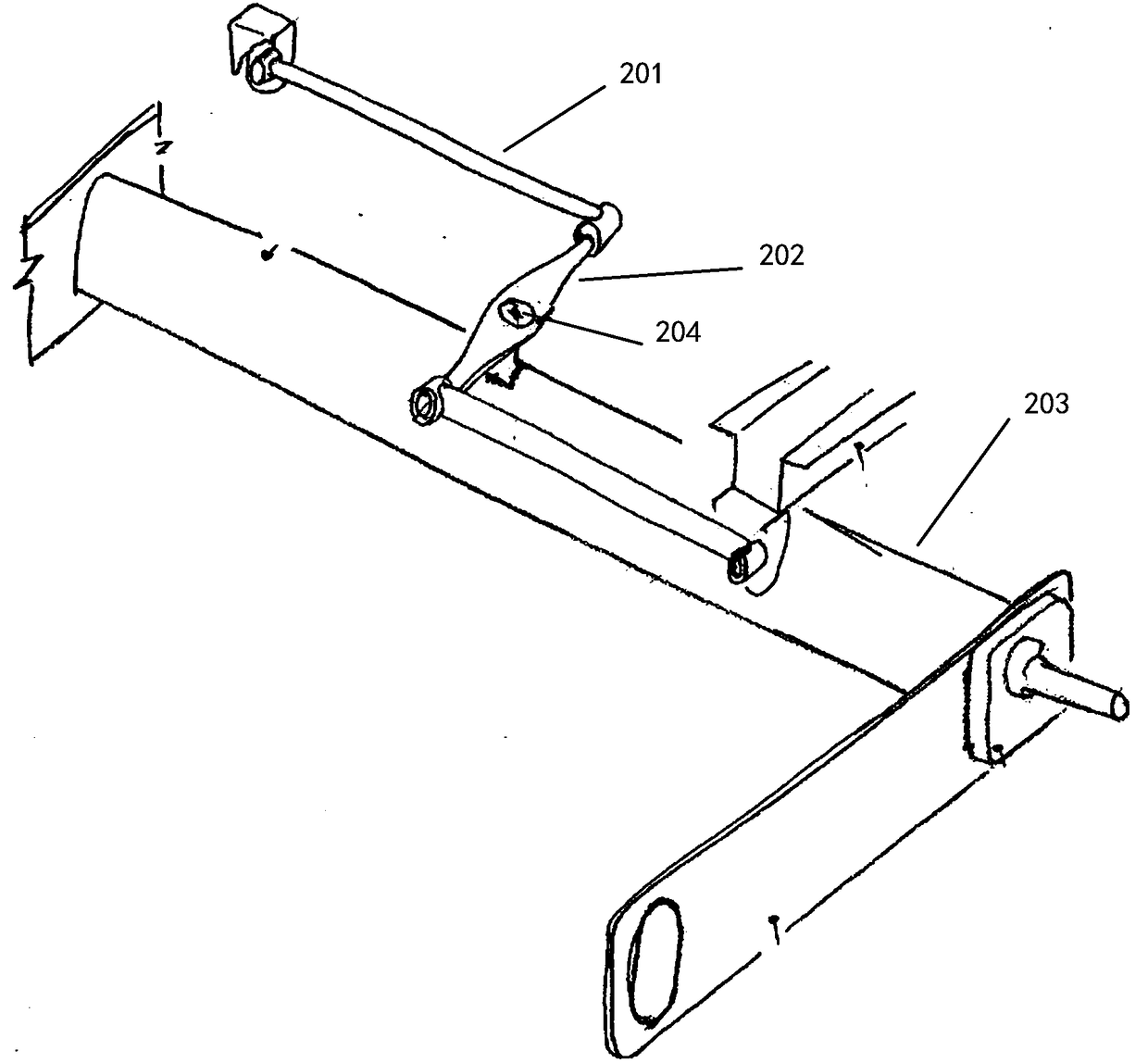
[0011] Such as figure 2 As shown, a Watt connecting rod installation structure includes a coupling lever 202 lying horizontally above the torsion beam. The middle part of the coupling lever is hinged to the torsion beam 203 through a fixed shaft 204 fixed on the upper side of the torsion beam. The two ends of the lever are respectively hinged to a push-pull rod 201 arranged horizontally, and the other ends of the two push-pull rods are respectively hinged to the vehicle bodies on both sides.

[0012] Most intuitively, since the Watt connecting rod installation structure is installed on the upper end of the torsion beam, it occupies the horizontal space above the torsion beam and does not need to occupy the longitudinal space of the chassis. Models with reserved longitudinal space have a wider range of application and make the structure of the bottom of the car more compact.

[0013] The operating principle of the Watt connecting rod installation structure is as follows: For ...


PUM


Abstract

A watt connecting rod installation structure comprises a coupled lever horizontally lying above a torsion beam. The middle portion of the coupled lever is hinged to the torsion beam through a fixed shaft fixed to the upper side of the torsion beam. Two horizontally-arranged push-pull rods are hinged to the two ends of the coupled lever. The other ends of the two push-pull rods are hinged to the portions, on the two sides, of an automobile body. Due to the fact that the structure is installed at the upper end of the torsion beam and occupies the horizontal space above the torsion beam, the longitudinal space of a chassis does not need to be occupied, the structure can be suitable for a vehicle model which is provided with a low base and cannot reserve a longitudinal space for a traditionalwatt connecting rod, the application range of the structure is wider, and the structure at the bottom of an automobile is more compact. Due to the fact that the two ends of each push-pull rod are directly connected to the automobile body, an axial support is additionally provided for each of the two sides equivalently, and connection is more stable.

Description

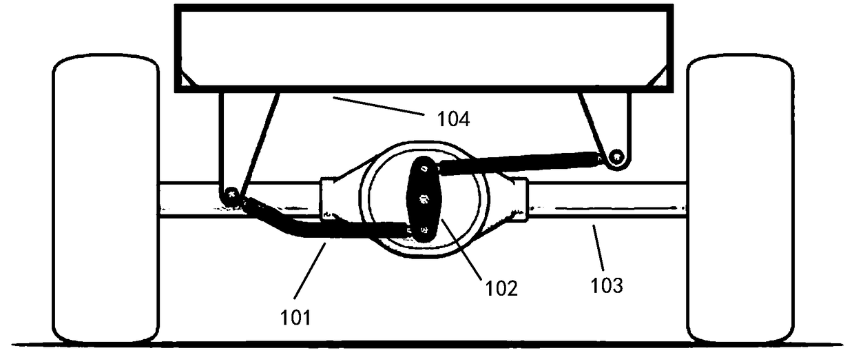
technical field [0001] The invention relates to a connection structure between an automobile body and a torsion beam, in particular to a Watt connecting rod installation structure. technical background [0002] Such as figure 1 As shown, in the current design of the rear torsion beam, the Watt link is a rod added to the left and right of the rear suspension. One end of the rod is installed at the end of the body and moves vertically with the body. The two rods 101 are connected by a coupling device 102, and the coupling device is connected to the torsion beam 103. The two rods interact with the coupling device to limit the range of motion of each other, so that the compression of the suspension on both sides can be reduced. and stretch. The compression and expansion ranges of the suspension 104 are made. The force on both sides of the suspension is more even, and the vehicle roll will be significantly reduced, which greatly improves the stability of the vehicle body, espe...

Claims


Application Information

Patent Timeline
IPC IPC(8): B60G21/05
CPCB60G21/052B60G2800/20B60G2800/24B60G2200/21
Inventor 波利斯泰纳·弗朗西斯·安东尼奥任玮罗四军林学延
Owner 马瑞利汽车零部件(广州)有限公司
Learn More