
Aligning method of mask and workpiece

A mask and workpiece technology, applied in the field of mask and workpiece alignment, can solve problems such as difficult screen mask ScM, workpiece expansion and contraction not necessarily fixed, printing solder, etc.

Active Publication Date: 2012-10-17
USHIO DENKI KK
View PDF9 Cites 3 Cited by
  • Summary
  • Abstract
  • Description
  • Claims
  • Application Information

AI Technical Summary

Problems solved by technology

[0059] If solder printing is performed in this state, the solder cannot be printed on the solder land formed on the workpiece, which may cause failures such as disconnection and short circuit.
[0060] On the other hand, if the position of the wiring pad to be projected on the workpiece is not changed in magnification corresponding to the reduction and enlargement of the wiring pattern accompanying the expansion and contraction of the workpiece when the wiring pad is formed by the exposure device, the wiring formed on the workpiece The position of the pattern does not match the position of the wiring pad, so this also becomes the cause of failures such as disconnection and short circuit
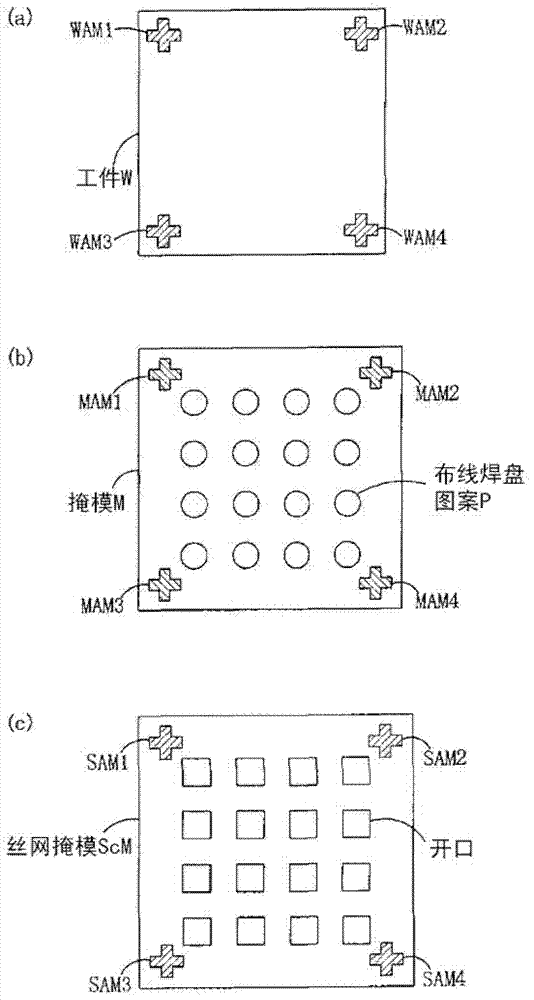
[0061] In addition, it is conceivable to set the size of the screen mask ScM in consideration of the expansion and contraction of the workpiece W so that the position of the opening of the screen mask and the position of the alignment mark SAM and the position of the expected wiring pad and the position of the workpiece mark WAM The screen mask ScM is produced in a consistent manner, but the amount of expansion and contraction of the workpiece is not necessarily fixed. Therefore, even if such a screen mask ScM can be produced, it is difficult to align the alignment mark SAM of the screen mask ScM with the workpiece formed on the workpiece W. There are many cases of marking the alignment of WAM
[0062] As mentioned above, in screen printing, solder is applied after the mask is brought into close contact with the workpiece, so the magnification of the mask pattern image to be projected cannot be changed according to the expansion and contraction of the workpiece as in projection exposure. If the size is very different from the mask used for screen printing, screen printing may not be possible
[0063] In addition, the above-mentioned problems also occur in the case of performing contact exposure or proximity exposure after the above-mentioned projection exposure.

Method used


Image

  • Aligning method of mask and workpiece
  • Aligning method of mask and workpiece
  • Aligning method of mask and workpiece

Examples


Embodiment Construction

[0093] Embodiments of the present invention will be described below. In the following embodiments, the case where the workpiece shrinks and the pattern shrinks is taken as an example for description. However, it is also applicable to the case where the pattern is enlarged due to the spread of the workpiece.

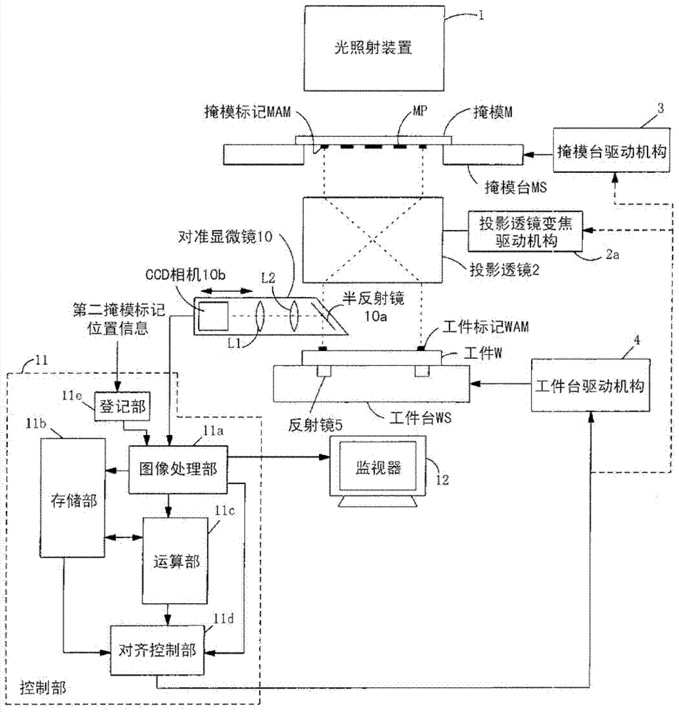
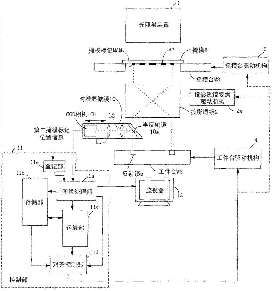
[0094] figure 1 , figure 2 It is a figure which shows the structure of the projection exposure apparatus concerning this invention. In addition, in the present embodiment, the exposure device exposes the entire workpiece (substrate) at one time, and four workpiece marks are formed, and accordingly, four mask marks are also formed.

[0095] In addition, in the following examples, the entire workpiece is exposed collectively, but it can also be applied to exposure in which the workpiece is divided into a plurality of exposure regions and the regions are sequentially exposed.

[0096] exist figure 1 , figure 2 where MS is the mask stage. A mask M formed with a mask...


PUM


Abstract

The invention provides an aligning method of mask and workpiece, with which the position of images formed on the workpiece through projection exposure, the position of images formed through former exposure processing, and the position of mask images for screen printing in the next processing will not have large deviation. At the time of aligning a projection exposure device, zoom ratio for enlarging or reducing projection of the mask (M) images can be adjusted. Accordingly, the sum of deviation value (dR) of the mask mark (MAM1-4) and work mark (WAM1-4) and the deviation value (dM) of the position of mask mark (MAM1-4) and the reference position of the mask mark (SAM1-4) of screened mask used in the next processing can be the minimum, and the aligning of the mask (M) and the workpiece (W) can be achieved by moving the mask (M) or the workpiece (W).

Description

technical field [0001] The present invention relates to a method for aligning a mask and a workpiece in a projection exposure apparatus for exposing a workpiece by projecting a mask pattern, and more particularly to a method for aligning a mask and a workpiece in such a manner that the size of the mask can be adjusted by expanding and contracting during the processing process. The workpiece that has changed is the target, and the alignment in the next process is considered when performing the above-mentioned alignment. In this way, screen printing, contact exposure, and proximity exposure such as soldering are performed in the next process of the projection exposure process. Even in the case of such a task of transferring the mask pattern onto the workpiece by contacting or approaching the workpiece with the mask of such a fixed size, the above-described alignment of the mask with the fixed size and the workpiece can be performed without causing large deviations. Background t...

Claims


Application Information

Patent Timeline
IPC IPC(8): G03F7/20G03F9/00
CPCG03F7/70775G03F9/7003G03F9/7023G03F9/7073G03F9/7084G03F9/7088
Inventor 三盐亮一井上丰治
Owner USHIO DENKI KK
Learn More