
RFID label detection equipment

A technology of RFID tags and testing equipment, which is applied in the field of testing equipment, can solve the problems of low-speed operation, electronic label shutdown and rejection, and the inability to ensure the stability of quality inspection at all times, so as to achieve the effect of providing quality

Inactive Publication Date: 2012-10-17
BROTECH GRAPHIC
View PDF2 Cites 21 Cited by
  • Summary
  • Abstract
  • Description
  • Claims
  • Application Information

AI Technical Summary

Problems solved by technology

Existing testing of printing quality adopts manual methods. The usual method is: inspectors place the cut labels on the rewinder and keep it running at a low speed. Operators observe the appearance quality of the electronic labels with naked eyes. The electronic labels will be rewinded, and the electronic labels with quality problems will be immediately shut down and removed
There are many shortcomings in the manual detection method, the two most critical points are the low detection efficiency and the inability to ensure the stability of quality detection at all times
The reason why the detection efficiency is low is that most of the electronic tags have small images and texts. If the detection speed is slightly faster, the naked eye will often be unable to distinguish some small defects, resulting in missed detection.
There is also a way to detect the surface printing quality of RFID tags through testing equipment, but this method can only detect the surface printing quality of RFID tags, and cannot reliably fix and contact physical characteristics between the chip and the antenna. to test

Method used


Image

  • RFID label detection equipment

Examples


Embodiment Construction

[0012] The present invention will be further described below in conjunction with the description of the drawings and the specific embodiments.

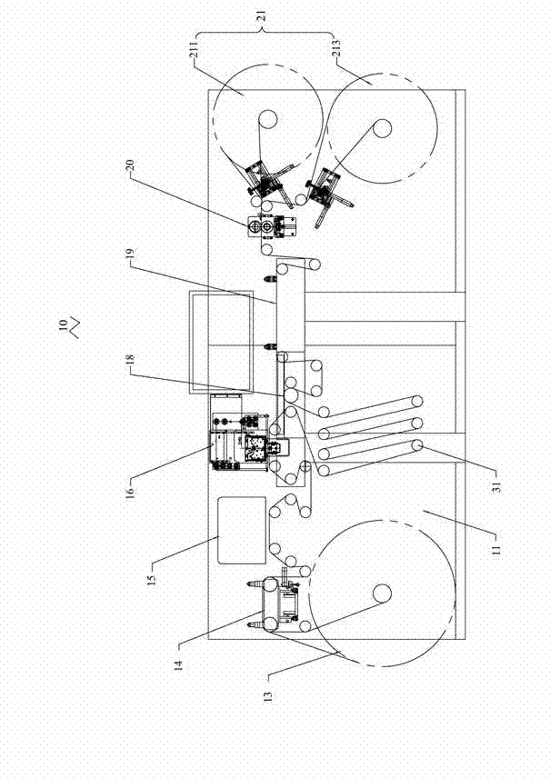
[0013] See figure 1 The present invention provides an RFID tag detection device 10, which includes a frame 11, an unwinding unit 13 and a winding unit 21 respectively arranged at both ends of the frame 11. The unwinding unit 13 and the rewinding unit 21 are further provided with a correction unit 14, a label conduction detection unit 15, a visual detection unit 16, a main traction unit 18, and a label changing platform 19 in sequence. A paper guide roller 31 for conveying printing materials is provided between each unit.

[0014] The unwinding unit 13 includes a rotating unwinding air expansion shaft and a first motor, and the unwinding air expansion shaft is used for placing roll-type printing materials. The working principle of the unwinding air expansion shaft is: a clamping block is arranged on the unwinding air expansion shaft, and ...


PUM


Abstract

The invention provides RFID label detection equipment used for carrying out detection upon RFID labels. The equipment comprises a frame, and an unreeling unit and a reeling unit respectively arranged on the two ends of the frame. A label conduction detection unit, a vision detection unit and a label changing platform are successively arranged between the unreeling unit and the reeling unit. Paper-guiding rollers are arranged between the units. The label conduction detection unit is arranged between the unreeling unit and the vision detection unit. According to the RFID label detection equipment provided by the invention, the printing quality of the labels, including variable information in the printed information, is detected by using the vision detection unit. The conduction performance of the labels is detected by using the label conduction detection unit. The unqualified labels are replaced by using the label changing platform. Therefore, efficiency and accuracy of the detection, and quality of the products can be ensured.

Description

Technical field [0001] The invention relates to a detection device, in particular to an RFID tag detection device. Background technique [0002] With the development of science and technology, RFID tags have been more and more widely used. Because RFID tags are read and written through radio frequency identification technology, good printing quality and good physical characteristics are crucial to their use. The existing printing quality inspection uses manual methods. The usual method is: the inspector places the cut small roll labels on the rewinder and keeps it running at a low speed. The operator observes the appearance quality of the electronic labels with the naked eye and is qualified. The electronic tags will be rewound, and the electronic tags with quality problems will be shut down immediately and removed. There are many shortcomings in manual detection methods. The two most critical points are low detection efficiency and the inability to guarantee the stability of qu...

Claims


Application Information

Patent Timeline
Patent Type & Authority Applications(China)
IPC IPC(8): G01N21/89G01R31/02
Inventor 李新
Owner BROTECH GRAPHIC
Learn More