
Coal mining machine

A technology for a shearer and a fuselage, which is applied in the field of shearers, can solve the problems of large torque of traveling wheels, reduced production efficiency, large impact of traveling wheels, etc., and achieves reasonable stress on the whole machine, enhanced applicability, and increased contact. area effect

Inactive Publication Date: 2012-10-17
SANY HEAVY EQUIP
View PDF5 Cites 7 Cited by
  • Summary
  • Abstract
  • Description
  • Claims
  • Application Information

AI Technical Summary

Problems solved by technology

[0004] 1. During the meshing process of the road wheel and the pin row, the pitch of the pin teeth at the joint between the pin row and the pin row has a greater change than the standard pitch, resulting in a greater impact on the road wheel, making the road wheel often abnormal fracture;
[0005] 2. The walking part is installed on the gob side, which will cause the traveling wheel to bear a large torque and break easily
[0007] Therefore, this structure often causes the traveling wheels to break, resulting in downtime for refurbishment and reduced production efficiency

Method used


Image

  • Coal mining machine
  • Coal mining machine

Examples


Embodiment Construction

[0034] In order to understand the above-mentioned purpose, features and advantages of the present invention more clearly, the present invention will be further described in detail below in conjunction with the accompanying drawings and specific embodiments.

[0035] In the following description, many specific details are set forth in order to fully understand the present invention. However, the present invention can also be implemented in other ways different from those described here. Therefore, the protection scope of the present invention is not limited by the specific details disclosed below. EXAMPLE LIMITATIONS.

[0036] The present invention will be further described below in conjunction with the accompanying drawings and embodiments. It should be noted that, in the case of no conflict, the embodiments of the present application and the features in the embodiments can be combined with each other.

[0037] Such as figure 1 , figure 2 As shown, the embodiment of the pr...


PUM


Abstract

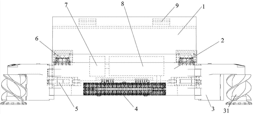
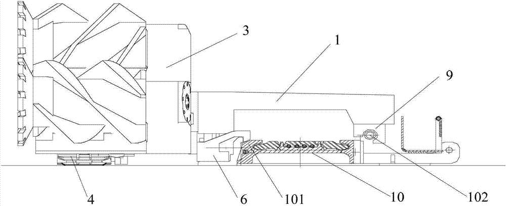
The invention provides a coal mining machine used for the coal mining field, comprising a bridge, a machine body and a cutting part, wherein one side of the machine body is movably connected with a scarper conveyor by the bridge, the other side of the machine body opposite to the bridge is provided with the cutting part; the coal mining machine further comprises a track travelling part and a guiding skid shoe, wherein the track travelling part is arranged on the machine body on the same side with the cutting part in order to realize the travelling and supporting of the coal mining machine; the guiding skid shoe is arranged on the machine body of the lower side of the bridge, is matched with the scraper conveyor and is capable of moving back and forth along the scrap conveyor. With the adoption of the coal mining machine, the contact area between the coal mining machine and the ground is increased, the engaging of rigid travelling wheel and pin row is replaced by the flexible track moving part, in this way, the wheel row impact in the travelling process is eliminated, the problem that the moving wheel is likely to break in the running process is solved, and the running stability of the coal mining machine is improved.

Description

technical field [0001] The invention relates to the field of coal mining machinery, in particular to a coal shearer. Background technique [0002] At present, most floor-climbing shearers use driving wheels to drive the traveling wheels, and the traveling wheels mesh with the pin row of the scraper conveyor to realize left and right walking. Travel along the conveyor, that is, the usual cycloidal wheel-pin-rail walking method. [0003] This cycloidal wheel-pin-rail walking mode, which uses the walking wheel and the pin row to mesh and cooperate with the guide shoe, to realize the coal shearer walking, has the following technical problems: [0004] 1. During the meshing process of the road wheel and the pin row, the pitch of the pin teeth at the joint between the pin row and the pin row has a greater change than the standard pitch, resulting in a greater impact on the road wheel, making the road wheel often abnormal fracture; [0005] 2. The traveling part is installed on ...

Claims


Application Information

Patent Timeline
Patent Type & Authority Applications(China)
IPC IPC(8): E21C29/22E21C35/12E21C25/68E21C25/06
Inventor 孙立柱尹力徐明昱
Owner SANY HEAVY EQUIP
Learn More