Signal detection method and device of MIMO (multiple input multiple output) system

A signal detection and symbol technology, which is applied in the signal detection field of MIMO system, can solve the problems of high computational complexity of the breadth-first algorithm, reduce the number of reserved nodes, and limit the number of visited nodes, so as not to reduce the detection performance, and the hardware implementation circuit is simple , the effect of low power consumption

Inactive Publication Date: 2012-10-10
PEKING UNIV
View PDF3 Cites 13 Cited by
  • Summary
  • Abstract
  • Description
  • Claims
  • Application Information

AI Technical Summary

Problems solved by technology

However, the computational complexity of the breadth-first algorithm is still very large, how to further reduce the complexity without affecting the performance is a hot issue in its application
[0007] At present, there are some simplified methods for the K-best SD algorithm. Luis G.Barbero et al. proposed an FSD algorithm with a limited number of nodes expanded by each node (L.G.Barbero and J.S.Thompson, "A Fixed-Complexity MIMO Detector Based on the Complex Sphere Decoder,"2006IEEE 7th Workshop on Signal Processing Advances in Wireless Communications, Cannes, France: 2006, pp.1-5.), to a certain extent reduces the number of nodes visited during the decoding process, but only in the number of reserved paths When there are many times, it is closer to the performance of the K-best SD algorithm, and at this time the computational complexity is relatively high
[0008] Cong Xiong et al proposed an algorithm that reduces the number of reserved nodes in the FSD algorithm as the number of search layers increases (Cong Xiong, Xin Zhang, Kai Wu, and Dacheng Yang, "A simplified fixed-complexity sphere decoder for V-BLAST systems, "Communications Letters, IEEE, vo1.13, 2009, pp.582-584.), this algorithm does not have enough theoretical basis for FSD to reduce the number of reserved nodes, and the reduced number of visited nodes is relatively limited

Method used


Image

  • Signal detection method and device of MIMO (multiple input multiple output) system
  • Signal detection method and device of MIMO (multiple input multiple output) system
  • Signal detection method and device of MIMO (multiple input multiple output) system

Examples


Embodiment Construction

[0043] The specific implementation manners of the present invention will be further described in detail below in conjunction with the accompanying drawings and embodiments. The following examples are used to illustrate the present invention, but are not intended to limit the scope of the present invention.

[0044] figure 1 Shown is a flowchart of a signal detection method for a MIMO system according to an embodiment of the present invention, as figure 1 As shown, the method includes the following steps:

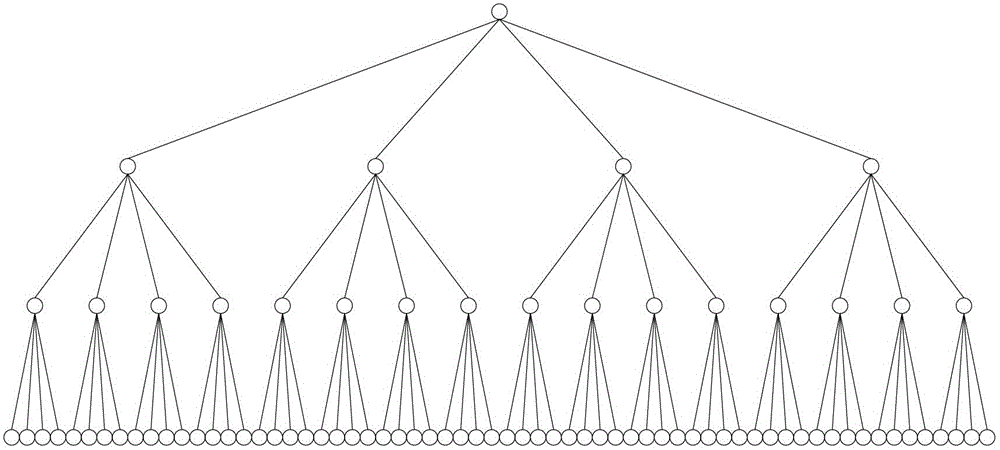
[0045] S1. Process the received signal and use the known channel matrix and possible transmission symbols to form a search tree;

[0046] Specifically: each row of the channel matrix is ​​sorted, and then the sorted channel matrix is ​​triangulated using the possible transmission symbols to form a search tree, and the sorting method is from small to large (if all possible node numbers in this layer not greater than K) / gain from large to small (if the number of all possibl...


PUM


Abstract

The invention relates to the technical field of signal detection and discloses a signal detection method and device of an MIMO (multiple input multiple output) system, wherein the method comprises the following steps: S1. constructing a search tree by utilizing a known channel matrix; S2. searching the Nth layer of the search tree; S21. dividing K nodes into M groups; S22. expanding sub nodes of the Nth layer of code according to the principle that the number of expanding sub nodes in all group of nodes are equal, and the number of expanding sub nodes in different groups of nodes is decreased sequentially from M; S23. sequencing according to the Euclidean distance between partial receiving vectors and partial transmitting vectors corresponding to all expanding sub nodes, and reserving K sub nodes of which the Euclidean distance is less than the threshold for the search of next layer; and S3. searching all the layers completely according to the modes of the steps S21-S23, and searching for the path with the minimum Euclidean distance from the paths consisting of sub nodes as the search results. According to the invention, the signal detection complexity is lowered and the detection efficiency of data receiving is improved.

Description

technical field [0001] The present invention relates to the technical field of signal detection, in particular to a signal detection method and device for a MIMO system. Background technique [0002] Multiple-input multiple-output (MIMO) technology can double the transmission rate without increasing the frequency band. Today, frequency resources are increasingly tight. Therefore, MIMO technology is considered to be the most important physical layer technology in the next generation of broadband wireless communication technology. one. [0003] In a MIMO system, in order to improve the reliability of source information transmission, at the sending end, the signal to be transmitted is firstly subjected to channel coding that can provide error correction capabilities, and then space-time / space-frequency / space-time-frequency coding, and then multiple The transmitting antennas transmit at the same time or in a certain time sequence. At the receiving end, the signals from the sen...

Claims


Application Information

Patent Timeline
IPC IPC(8): H04B7/06H04B7/08
Inventor 毛新宇吴建军
Owner PEKING UNIV
Why Eureka
Try Eureka