
Power system reactive power optimization method based on individual optimal position self-adaptive variation disturbance particle swarm algorithm

A particle swarm algorithm and optimal position technology, applied in reactive power compensation, reactive power adjustment/elimination/compensation, calculation, etc., can solve problems such as computational complexity and real-time performance that cannot meet reactive power optimization

Inactive Publication Date: 2012-10-10
SOUTHWEST JIAOTONG UNIV
View PDF3 Cites 38 Cited by
  • Summary
  • Abstract
  • Description
  • Claims
  • Application Information

AI Technical Summary

Problems solved by technology

With the rapid development and urgent needs of power systems, conventional optimization methods cannot meet the computational complexity and real-time performance of reactive power optimization.

Method used


Image

  • Power system reactive power optimization method based on individual optimal position self-adaptive variation disturbance particle swarm algorithm
  • Power system reactive power optimization method based on individual optimal position self-adaptive variation disturbance particle swarm algorithm
  • Power system reactive power optimization method based on individual optimal position self-adaptive variation disturbance particle swarm algorithm

Examples


Embodiment Construction

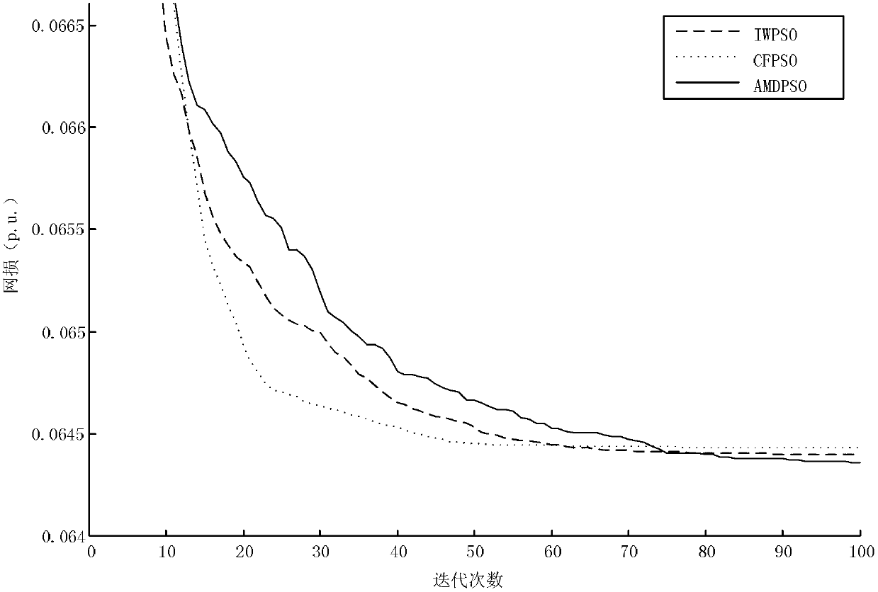
[0044] Taking the IEEE 30-node system as an example, the node network parameters are derived from [Zhang Boming, Chen Shousun, Yan Zheng. Advanced electrical network analysis [M]. Beijing: Tsinghua University Press, 2007: 325-328]. The system has 30 nodes, 41 branches, 21 load nodes, 6 generators, 4 adjustable transformers, and two capacitor reactive power compensation nodes. Set the initial transformation ratio of the adjustable transformer to 1, the initial voltage of the generator to 1, and the initial reactive power compensation point to 0, and the initial network loss is P LOSS = 0.0844.

[0045] (1) Establishing a reactive power optimization model, starting from economic performance, taking the minimum network loss as the reactive power optimization mathematical model. Considering the out-of-bounds of node voltage and generator reactive output, the penalty function is used to deal with the out-of-bounds of node voltage and generator's reactive output. The mathematica...


PUM


Abstract

The invention discloses a power system reactive power optimization method based on an individual optimal position self-adaptive variation disturbance particle swarm algorithm. The power system reactive power optimization method comprises the following steps: establishing a power system inactive optimization model; inputting power grid parameters to form an initial population, and calculating a grid damage value corresponding to all particles of the population; recording an individual optimal position and an individual optimal grid damage value as well as a global optimal position and a global optimal grid damage value of the initial population; updating the speeds and the positions of the particles; calculating a grid damage value corresponding to each particle of the population and updating the individual optimal position and the individual optimal grid damage value as well as the global optimal position and the global optimal grid damage value of the population; and judging whether to carry out the variation according to a self-adaptive criterion. The method is rapid in convergence rate, high in calculation precision and good in stability; the problem of inactive optimization of the power system can be solved effectively; and the method can be used for improving the electricity transmission efficiency of the power system and reducing the network loss configuration real-time operation control in the power system.

Description

technical field [0001] The invention relates to power system design, in particular to the technical field of improving power system transmission efficiency, reducing network loss and configuring real-time operation methods. Background technique [0002] With the increasing scale of the power grid, the structure of the power grid is also becoming more and more complex. Users require more reliable power supply and better power quality. Voltage quality is an important index in power quality evaluation. Excessive voltage offset or fluctuation will cause a series of adverse effects on the power system, such as unstable operation, increased transmission line loss, and increased power loss. Therefore, in order to ensure the healthy operation of the power system, the voltage deviation cannot exceed the specified rated value. However, the reactive power balance of the power system determines the level of operating voltage, that is, the reactive power output of reactive sources mus...

Claims


Application Information

Patent Timeline
Patent Type & Authority Applications(China)
IPC IPC(8): H02J3/18G06N3/00
CPCY02E40/30
Inventor 刘志刚曾嘉俊柳杰
Owner SOUTHWEST JIAOTONG UNIV
Learn More