


Quick Research
Generate reliable direction feasibility study reports for your R&D in just a few steps.

Technical Q&A
Discover and master advanced knowledge NOW. Basics, ideas, possibilities, all at once.

Find Solutions
As an expert in R&D theories, this can generate solutions to your technical problems instantly.

Evaluate Feasibility
Analyze your overall solution with one click, know your potential R&D risks in advance.

Monitor Landscape
Get weekly tech updates, stay abreast of the latest tech innovations and key insights.
Two-stage piston pusher centrifuge accelerating disc flow field visualization method
A two-stage piston and centrifuge technology, applied in special data processing applications, instruments, electrical digital data processing, etc., to achieve intuitive programming, strong compatibility, and wide applicability
- Summary
- Abstract
- Description
- Claims
- Application Information
AI Technical Summary
Problems solved by technology
Method used
Image

Examples
Embodiment 1
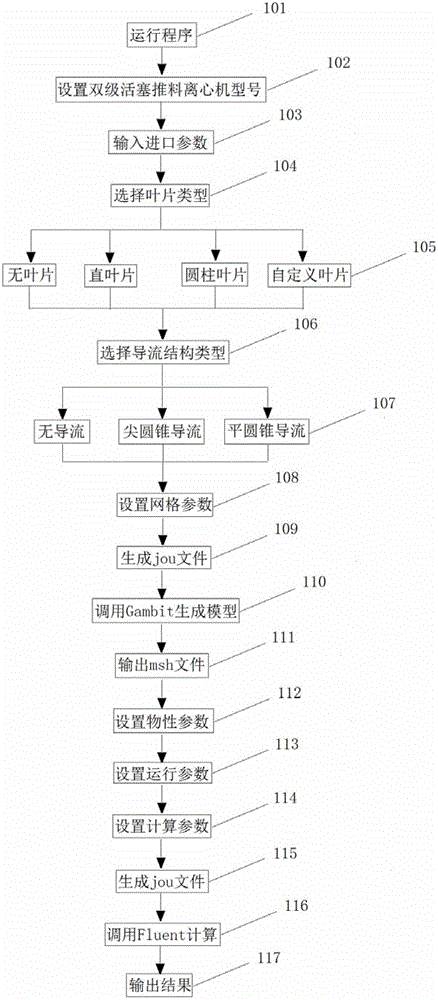
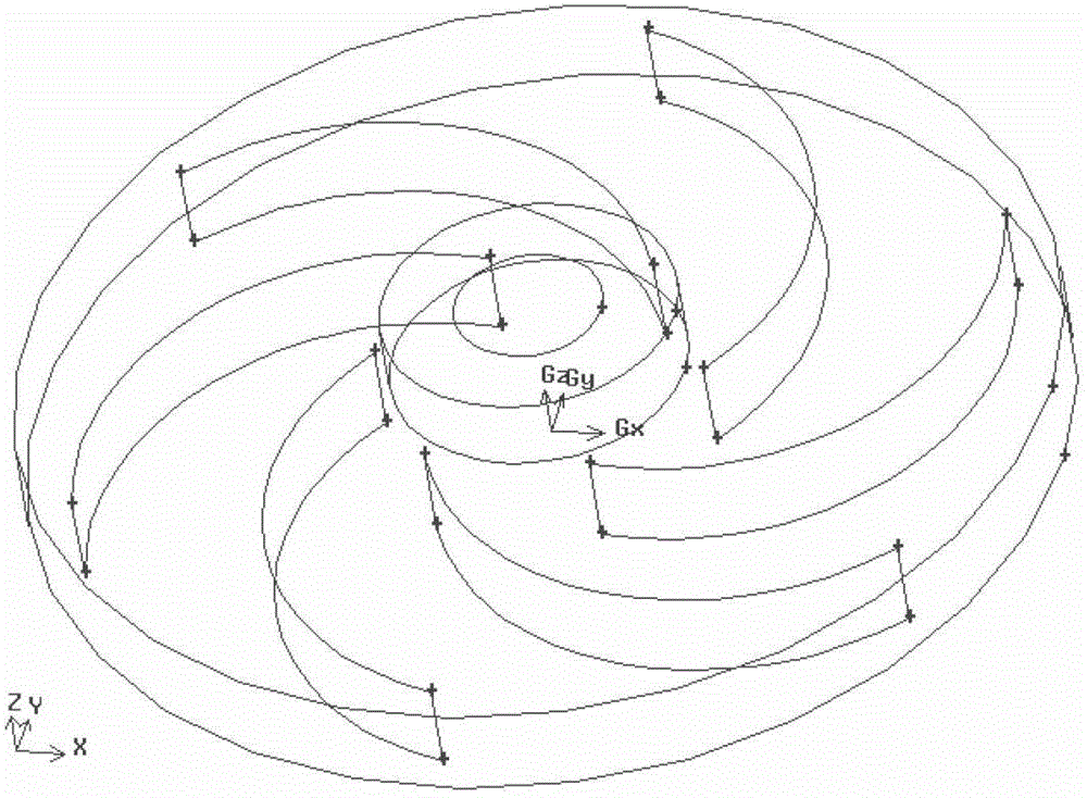
[0081] Here, the application of this method is explained by taking the acceleration plate of the P-60 two-stage piston pusher centrifuge as an example. In this example, the acceleration disk has no guide structure, the blade type is a cylindrical blade, and the blade curve is a controllable wrap angle curve. as per figure 1 The steps shown are set up and calculated.
[0082] Step 101, start the parameterized modeling calculation program of the accelerator disk;
[0083] Step 102, select the model of the two-stage piston pusher centrifuge as P-60 through the interface operation, the corresponding drum radius is 280mm, and the input model height is 50mm;
[0084] Step 103, set model inlet parameters, material inlet radius R 10 40mm, gas phase inlet radius R 20 is 80mm, and the length of the inlet section is 40mm;
[0085] Step 104, select the blade type as cylindrical blade;
[0086] Step 105, setting blade parameters, inner radius R 1 90mm, outer radius R 2 is 260mm, th...
Embodiment 2
[0100] Embodiment 2 improves on the basis of Embodiment 1, and operates as follows:
[0101] Steps 101-105 are the same as in Embodiment 1;
[0102] Step 106, setting the diversion structure as pointed cone diversion, the height of the diversion structure is 45mm, which is 50mm smaller than the height of the blade, and the radius of the bottom surface of the diversion structure is 80mm, which is 90mm smaller than the inner radius of the blade;
[0103] Steps 107-116 are the same as in Embodiment 1;
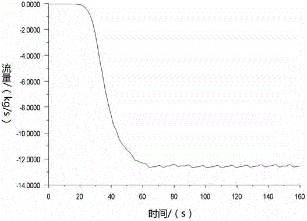
[0104] Step 117, extract flow field simulation results Figure 8 It is the change of material mass flow rate at the outlet with time. The shorter the time required for the material to reach the maximum flow rate, the faster the acceleration plate accelerates the material, and the smaller the accumulation of materials inside the accelerator plate; Figure 9 is the material tangential velocity distribution at the outlet; Figure 10 is the material radial velocity distribution at ...
PUM
| Property | Measurement | Unit |
|---|---|---|
| Density | aaaaa | aaaaa |
| Particle size | aaaaa | aaaaa |
Abstract
Description
Claims
Application Information
 - R&D Engineer
- R&D Manager
- IP Professional
- Industry Leading Data Capabilities
- Powerful AI technology
- Patent DNA Extraction
Browse by: Latest US Patents, China's latest patents, Technical Efficacy Thesaurus, Application Domain, Technology Topic, Popular Technical Reports.
© 2024 PatSnap. All rights reserved.Legal|Privacy policy|Modern Slavery Act Transparency Statement|Sitemap|About US| Contact US: help@patsnap.com