
Light shaping apparatus and laser light source

A shaping device and laser technology, applied in the field of optics, can solve problems such as the inability to freely adjust the spot size, and achieve the effect of realizing the spot size

Active Publication Date: 2012-10-10
APPOTRONICS CORP LTD
View PDF7 Cites 22 Cited by
  • Summary
  • Abstract
  • Description
  • Claims
  • Application Information

AI Technical Summary

Problems solved by technology

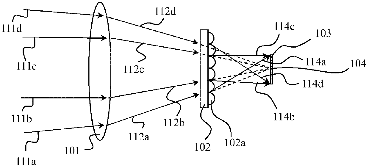
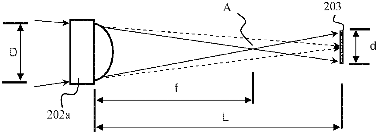
[0008] The main technical problem solved by the present invention is to propose a light shaping device, which solves the problem that the existing light shaping device cannot freely adjust the spot size

Method used


Image

  • Light shaping apparatus and laser light source
  • Light shaping apparatus and laser light source
  • Light shaping apparatus and laser light source

Examples


Embodiment Construction

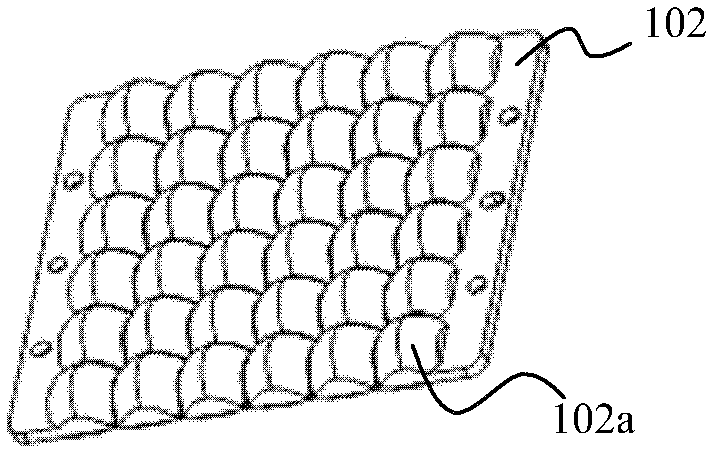
[0021] The present invention proposes a light shaping device, which is used to focus the incident light on a specific focal plane and form a spot of a specific shape; the light shaping device includes a focusing component, and the focusing component is used to converge the incident light on the focal plane also include at least one arc mirror array between the focusing part and the optical path of the focusing plane, the arc mirror array includes a plurality of arc mirror units arranged side by side, and the arc mirror unit is used to emit light from the focusing part The light incident on the arc mirror unit is projected onto the focusing plane to form sub-spots corresponding to the arc mirror unit. Wherein, the shape of the sub-spot is similar to the shape of the corresponding curved mirror unit.

[0022] The following will describe in detail according to specific embodiments.

[0023] The light shaping device of the first embodiment of the present invention is as Figure 1...


PUM


Abstract

The invention provides a light shaping apparatus which is used to focus incident light on a specific focusing plane and form a light spot with a specific shape. The apparatus comprises a focusing part and a cambered surface lens array located between the focusing part and a light path of the focusing plane. The cambered surface lens array comprises a plurality of cambered surface lens units. The cambered surface lens unit is used to project the light which is incident into the cambered surface lens and is emitted from the focusing part on the focusing plane so as to form the sub-light-spot corresponding to the cambered surface lens unit. The shape of the sub-light-spot is similar to the shape of the corresponding cambered surface lens unit. The invention also provides a laser light source. The laser light source comprises the light shaping apparatus so as to focus the laser on the specific focusing plane and form the light spot with the specific shape. In the light shaping apparatus and the laser light source of the invention, the cambered surface lens array is used to make the light which is emitted from the focusing part form the light spot with the specific shape on the focusing plane respectively so as to realize the shaping of the light spot.

Description

technical field [0001] The present invention relates to the field of optics, in particular to a light shaping device and a laser light source that uses the light shaping device to output a spot of a specific shape Background technique [0002] At present, lasers are used in many occasions, such as lithography, projection display and so on. In these application fields, it is often required that the laser light source emits a uniform spot of a specific shape. For example, US Pat. No. 7,547,114 discloses a projection display light source, which uses excitation light to excite a fluorescent pink wheel to alternately generate monochromatic light. In this light source, the shape of the spot where the excitation light irradiates on the fluorescent pink wheel is preferably a rectangle with an aspect ratio of 4:3 or 16:9, because this shape is the same as that of the light valve at the rear end of the projection display. The local energy density of the excitation light irradiated o...

Claims


Application Information

Patent Timeline
Patent Type & Authority Applications(China)
IPC IPC(8): G02B27/09F21V5/00F21V9/10G03B21/00G03B21/14F21V9/40
Inventor 胡飞
Owner APPOTRONICS CORP LTD
Learn More