
Gearbox steering mechanism

A steering mechanism and gearbox technology, applied in mechanical equipment, gear transmission, belt/chain/gear, etc., can solve the problems of frequent use of steering mechanism, complex processing of intermediate gears, low production efficiency of parts, etc., and achieve novel structure, The effect of large transmission torque and high production efficiency

Inactive Publication Date: 2012-10-10
康章保
View PDF7 Cites 3 Cited by
  • Summary
  • Abstract
  • Description
  • Claims
  • Application Information

AI Technical Summary

Problems solved by technology

However, the steering mechanism of the harvester gearbox still has the common problem of the jaw clutch structure: the steering mechanism is frequently used, and the clutch jaws are frequently combined and separated, so that the joint surface of the clutch jaws wears extremely fast, and the clutch jaws close to the end face The side wears faster, forming a slope, which easily disengages the clutch teeth of the intermediate gear and the steering gear, resulting in a reduction in the transmitted torque; and the production efficiency of parts with clutch teeth is low, and the manufacturing cost is high
Now, some non-jaw clutch or non-differential gearbox steering mechanisms have also appeared. For example, Chinese patent application 200520116510.1 discloses a small-sized walking tractor internal gear steering mechanism. There are internal teeth on both sides of the inner surface, and the internal teeth on both sides mesh with the left and right steering gears respectively. It has the advantages of simple and compact structure, light operation, and flexible steering. However, the processing of the intermediate gear is more complicated and the manufacturing cost is higher.

Method used


Image

  • Gearbox steering mechanism
  • Gearbox steering mechanism
  • Gearbox steering mechanism

Examples


Embodiment Construction

[0029] The accompanying drawings disclose the specific structure of the present invention without limitation, and the present invention will be further described below in conjunction with the accompanying drawings.

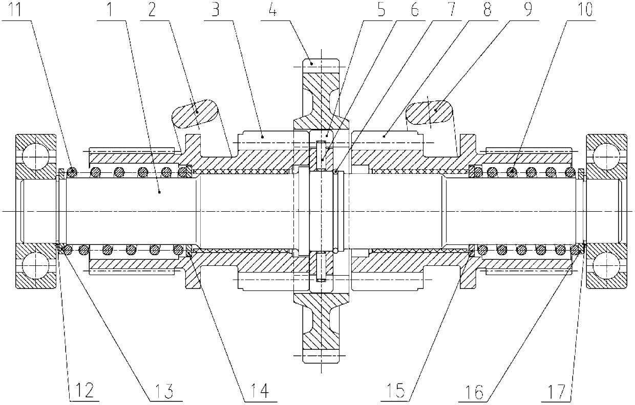
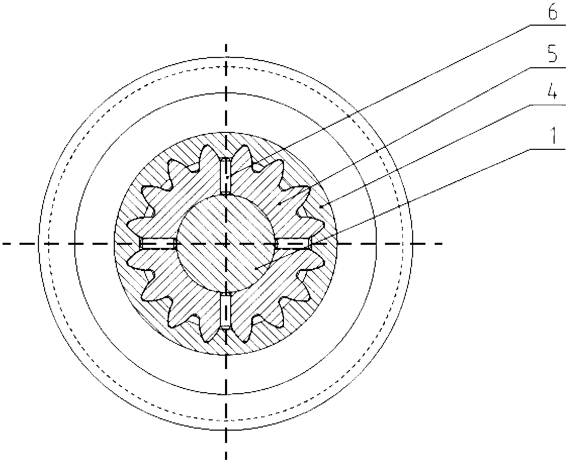
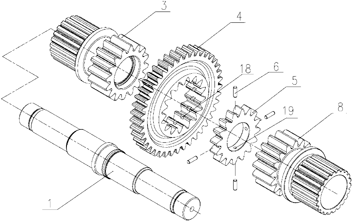
[0030] Such as Figure 1~4 As shown, the gearbox steering mechanism includes a steering shaft 1, which is coaxially arranged on the steering shaft 1 and has an intermediate gear 4 with internal teeth; the steering shaft 1 on both sides of the intermediate gear 4 is slidingly sleeved with left and right steering gears respectively. Gears 3 and 8; one side of the left and right steering gears 3 and 8 is provided with large teeth meshing with the internal teeth of the intermediate gear 4, and the other side is provided with small teeth; correspondingly provided on the left and right steering gears 3 and 8 Left and right steering forks 2, 9; left and right return springs 11, 10 are sleeved at both ends of the steering shaft 1; a coupling gear 5 is coaxially fixed on t...


PUM


Abstract

The invention relates to a gearbox steering mechanism on an agricultural machine, which comprises steering shafts 1 and an intermediate gear 4 which is coaxially arranged on the steering shafts 1 and is provided with internal teeth, wherein a left steering gear 3 and a right steering gear 8 are respectively sleeved on the steering shafts 1 at the two sides of the intermediate gear 4 in a sliding way; big teeth meshed with the internal teeth of the intermediate gear 4 are arranged at one sides of the left steering gear 3 and the right steering gear 8, and small teeth are arranged at the other sides; a left steering shift fork 2 and a right steering shift fork 9 are correspondingly arranged on the left steering gear 3 and the right steering gear 8; a left return spring 11 and a right return spring 10 are sleeved at the two ends of the steering shafts 1; and a connecting gear 5 is coaxially fixed on the steering shafts 1, and the connecting gear 5 is arranged between the left steering gear 3 and the right steering gear 8 and is meshed with the internal teeth of the intermediate gear 4. The gearbox steering mechanism has the advantages of novel structure, large transfer torque, long service life, good clutch performance, high production efficiency and low manufacturing cost.

Description

technical field [0001] The invention relates to the technical field of agricultural machinery, in particular to a gearbox steering mechanism. Background technique [0002] At present, the steering mechanism of the gearbox on the agricultural machinery mainly adopts the jaw clutch type and the differential type. The existing steering mechanism adopts the jaw clutch type, the intermediate gear has jaws on both sides, and the steering gear with jaws is installed on the left and right, and the intermediate gear is clutched with the steering gear through the jaws. For example, Chinese patent application 201120171478.2 discloses a harvester gearbox steering mechanism with a jaw clutch structure, although it changes the angle between the clutch teeth of the intermediate gear and the steering gear, and changes the angle of the intermediate gear. The way the clutch teeth cut into the angle makes the clutch teeth not easy to fall off, improves the clutch performance, and can reduce w...

Claims


Application Information

Patent Timeline
IPC IPC(8): F16H3/18
Inventor 康章保
Owner 康章保
Learn More