
Counterweight hammer and hoisting device

A technology of counterweight hammer and heavy hammer body, which is applied in the direction of balance weight, load hanging components, transportation and packaging, etc. It can solve the problems of inconvenient replacement, falling out of heavy hammer body, easy loss, etc., and achieves convenient disassembly and structural safety Reliable, low-cost results

Inactive Publication Date: 2012-10-10
SHANGHAI SANY TECH
View PDF6 Cites 8 Cited by
  • Summary
  • Abstract
  • Description
  • Claims
  • Application Information

AI Technical Summary

Problems solved by technology

The disassembly and assembly of the counterweight hammer with two half-barrel-shaped parts fastened together by bolts is cumbersome. Tools are required and the removed fasteners are not easy to keep and easy to lose. Pretending to be difficult
The left half limit block and the right half limit block are pivotally connected together by pin shafts, and the overall size of the counterweight hammer with a fan-shaped open-close structure is relatively large. When using multiple ratios, the outer diameter is easy to interfere, and the fasteners must be fixed reliably. On the limit blocks of the two halves, it is inconvenient to replace after rusting
The overall center of gravity of the weight hammer formed by the insertion of the weight body and the insert block is far away from the position of the lifting lug, resulting in excessive inclination of the weight, which causes serious friction with the wire rope. When the vibration is large, due to the large gap, The weight body is easy to come out of the plug

Method used


Image

  • Counterweight hammer and hoisting device
  • Counterweight hammer and hoisting device

Examples


Embodiment Construction

[0022] The present invention will be further described below in conjunction with the accompanying drawings and specific embodiments, but not as a limitation of the present invention.

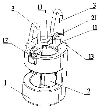
[0023] Such as figure 1 with figure 2 As shown, an embodiment of a counterweight hammer in the present invention, which includes a weight body 1 and an insert block 2, and the insert block 2 is integrated with the weight body 1 through the socket 11 on the weight body 1; the socket 11 The upper opening of the plug 2 exposes the top surface of the plug 2; there is a stopper on the socket of the weight body 1, and the stopper restricts the plug (2) from protruding from the top of the weight body (1); the top surface of the plug 2 A first hooking part 21 is provided, and a second hooking part 12 is provided on the weight body 1 at a position symmetrical to the first hooking part 21 with respect to the center of gravity of the counterweight of the height limiter. Through the first hooking part 21...


PUM


Abstract

The invention discloses a counterweight hammer and a hoisting device and belongs to the technical field of limit switch application in hoisting devices. The counterweight hammer comprises a counterweight hammer body 1 and an inserting block 2, wherein the inserting block 2 and the counterweight hammer body 1 are connected into a whole in an inserting mode through an inserting port 11 of the counterweight hammer body 1, the inserting port of the counterweight hammer body 1 is provided with a limiting member, the limiting member is used for preventing the inserting block 2 from falling out of the upper portion of the counterweight hammer body 1, a first hook member 21 is arranged at the top of the inserting port 2, and a second hook member 12 is arranged at a position of the counterweight hammer body 1, which is symmetric with the first hook member 21 relative to the gravity center of a height limiter counterweight hammer. The technical scheme has the advantages that the counterweight hammer body and the inserting block are formed in an inserting mode, and the disassembly is convenient and rapid; the inserting block is prevented from loosening and falling through a structure that the width of a spring hook is larger than that of the upper portion of the inserting port; the counterweight hammer body is prevented from loosening and falling from a working position through a hoisting lug of the spring hook, which is hung on the counterweight hammer body, and the structure is safe and reliable; and the whole counterweight hammer is a casting part, requirements for the surface are low and the cost is low.

Description

technical field [0001] The invention belongs to the technical field of application of a limit switch on lifting equipment, in particular to a counterweight hammer used for a height limiter and lifting equipment. Background technique [0002] The height limiter is a device used to limit the maximum height of the crane hook, and the counterweight is an important part of the height limiter. The existing height limiter counterweight generally adopts an assembled detachable structure. For example, the counterweight hammer with two semi-barrel parts fastened together by bolts, the left half limit block and the right half limit block are pivotally connected together by pin shafts to form a fan-shaped openable structure counterweight, or through The heavy hammer body and the insert block are inserted and formed, and the lifting lug is arranged on the counterweight hammer on the insert block. The disassembly and assembly of the counterweight hammer with two half-barrel-shaped parts...

Claims


Application Information

Patent Timeline
IPC IPC(8): F16F15/28B66C13/50
Inventor 张韵涵徐洪勇刘雪梅
Owner SHANGHAI SANY TECH
Learn More