Hydraulic oil temperature control device and control method and excavator comprising same

A control device and hydraulic oil technology, which is applied in the field of hydraulic oil temperature control devices and excavators, can solve the problems of accelerated aging of sealing materials, high oil temperature of hydraulic system, increased oil leakage, etc., and achieve the effect of convenient assembly

Inactive Publication Date: 2014-12-17
SHANGHAI SANY HEAVY IND
View PDF4 Cites 0 Cited by
  • Summary
  • Abstract
  • Description
  • Claims
  • Application Information

AI Technical Summary

Problems solved by technology

Excavators generally drive the actuator through the hydraulic system. The hydraulic oil used in the hydraulic system will absorb some heat generated by the operation of the actuator when the actuator is working, which will increase the temperature of the oil circuit of the entire hydraulic system, which will cause the viscosity of the oil to decrease and lubricate the parts. The oil film is destroyed, the oil leakage increases, the aging of the sealing material is accelerated, the gap between the kinematic pairs with different expansion coefficients in the hydraulic components becomes smaller, and the stagnation occurs, etc., which affect the performance and reliability of the hydraulic system.
[0003] Existing heat dissipation methods for excavator hydraulic oil mostly use engine-driven cooling fans for heat dissipation, and engine cooling water, air-to-air coolers, air-conditioning condensers, etc. are also used for heat dissipation by engine cooling fans. These radiators or Connected in series or in parallel, due to the limitation of the diameter of the cooling fan of the engine itself and the space installation position, it is difficult to arrange the layout of the radiator, resulting in poor heat dissipation and high oil temperature in the hydraulic system. The above problems cannot be solved

Method used


Image

  • Hydraulic oil temperature control device and control method and excavator comprising same

Examples


Embodiment Construction

[0025] The present invention will be further described below in conjunction with the accompanying drawings and specific embodiments, but not as a limitation of the present invention.

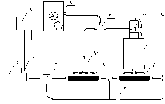
[0026] Such as figure 1 The hydraulic oil temperature control device in the illustrated embodiment of the present invention includes a main power source 1, a main radiator 2, a fan connected to the main power source 1 to increase the air flow of the main radiator, a control valve 3 and an oil tank 4, The oil inlet of the control valve 3 is connected to the main pump of the oil circuit (not marked in the figure), the oil outlet is connected to the oil inlet of the main radiator 2, and the oil outlet of the main radiator 2 is connected to the oil tank 4, which also includes auxiliary The heat dissipation device, the auxiliary heat dissipation device includes an auxiliary power source, an auxiliary radiator 6, a fan connected to the auxiliary power source to increase the air flow of the auxiliary r...


PUM


Abstract

The invention discloses a hydraulic oil temperature control device, and belongs to the technical field of heat dissipation of hydraulic systems. The hydraulic oil temperature control device comprises an auxiliary heat abstractor, wherein the auxiliary heat abstractor comprises an auxiliary power source, an auxiliary radiator and a fan which is connected with the auxiliary power source and is used for improving the air flow of the auxiliary radiator, a radiator electric control proportioning valve, a temperature sensor and a controller. The hydraulic oil temperature control device provided by the invention has the beneficial effects that the intelligent control of hydraulic oil temperature is realized, the real-time matching of the temperature and heat dissipation efficiency can be realized, the effective heat dissipation of a system is guaranteed, the engine power is saved, and the hydraulic oil temperature control device is more economical and reasonable. Hydraulic oil temperature is prevented from being at an extraordinarily high temperature; the problem that the ultrahigh hydraulic oil temperature affects the working efficiency of the excavator due to long-time operation can be avoided, and the damage to the hydraulic system sealing element can be reduced. The arrangement of an auxiliary cooling system is free from the limitation of the installation position, and the auxiliary radiator can be assembled conveniently on the space which is easy to be arranged.

Description

technical field [0001] The invention relates to a cooling device for a hydraulic system of an excavator, in particular to a hydraulic oil temperature control device and a control method and an excavator including the device. Background technique [0002] An excavator, also known as an excavating machine, is an earth-rock machine that uses a bucket to excavate materials that are higher or lower than the bearing surface, and load them into transport vehicles or unload them to the stockyard. The excavated materials are mainly soil, coal, silt, and pre-loosened soil and rock. With the development of construction machinery, excavators have become one of the most important types of construction machinery in engineering construction. Excavators generally drive the actuator through the hydraulic system. The hydraulic oil used in the hydraulic system will absorb some heat generated by the operation of the actuator when the actuator is working, which will increase the temperature of ...

Claims


Application Information

Patent Timeline
Patent Type & Authority Patents(China)
IPC IPC(8): E02F9/22
Inventor 李中才黄昌黎
Owner SHANGHAI SANY HEAVY IND
Why Eureka
Try Eureka