Cooling water circulation system of injection molding workshop
A technology of cooling water circulation pipe and circulation system, applied in the field of cooling water circulation system, can solve the problems of lower production efficiency, increase of production cost, energy waste, etc., and achieve the effect of reducing suction resistance and saving energy consumption
- Summary
- Abstract
- Description
- Claims
- Application Information
AI Technical Summary
Problems solved by technology
Method used
Image
Examples
Embodiment 1)
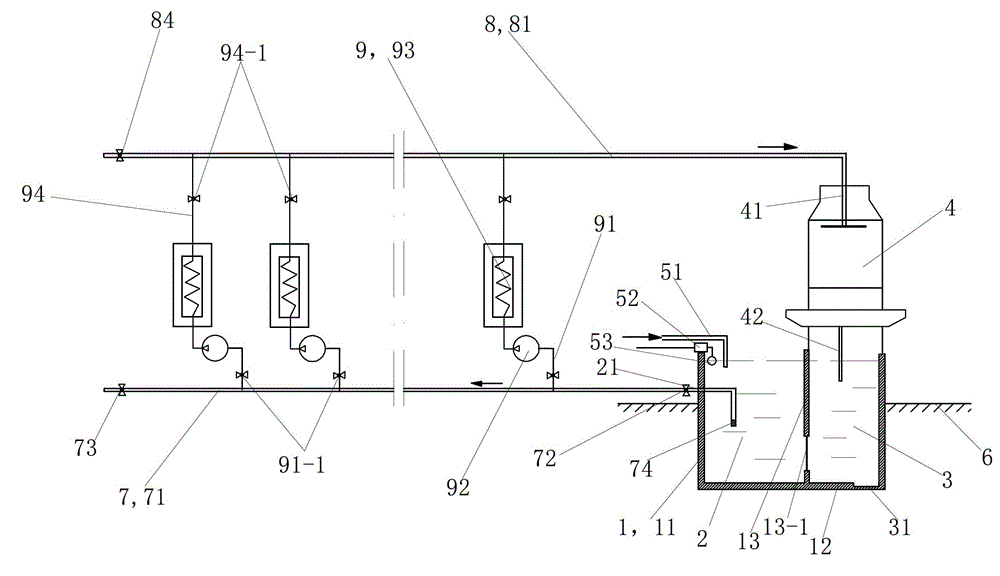
[0035] see figure 1 The cooling water circulation system of the injection molding workshop of this embodiment includes a reservoir, a cooling water circulation pipeline, a cooling tower 4 and a supplementary water supply pipeline 51.
[0036] The reservoir includes a pool body 1. The pool body 1 includes a pool wall 11, a pool bottom 12 and a partition wall 13, the bottom end of the partition wall 13 is fixed on the pool bottom 12, and the height of the partition wall 13 is the same as the height of the pool wall 11. The 1 / 2 to 2 / 3 part of the pool body 1 is located below the ground 6, and the remaining part is located above the ground 6, which not only ensures sufficient water storage, but also covers a small area; in this embodiment, the upward direction of the pool body 1 The height of the part protruding from the ground 6 is 1200 mm, and the depth of the part below the ground 6 is 2000 mm.
[0037] The tank body 1 is divided into two parts by a partition wall 13, which are a s...
Embodiment 2)
[0057] The rest of this embodiment is the same as the first embodiment, except that it also includes a replenishment pool, a water pumping pipe, a replenishment water pump, a miniature limit switch 52 and a float 53. The miniature limit switch 52 controls the opening and closing of the make-up water pump. The figure does not show the make-up tank, the pumping pipe and the make-up pump.
[0058] The inlet of the make-up water pump is connected with the pumping pipe, the lower part of the pumping pipe is vertically arranged, and the lower port extends into the lower part of the replenishing pool. The water outlet of the makeup water pump is connected to the water inlet of the supplementary water supply pipe 51. The floating ball 53 floats in the water supply tank 2, and the upper part of the floating ball 53 is connected to the swing rod of the miniature limit switch 52 through a wire. When the water level in the water supply tank 2 drops, the floating ball 53 drops accordingly, ...
Embodiment 3)
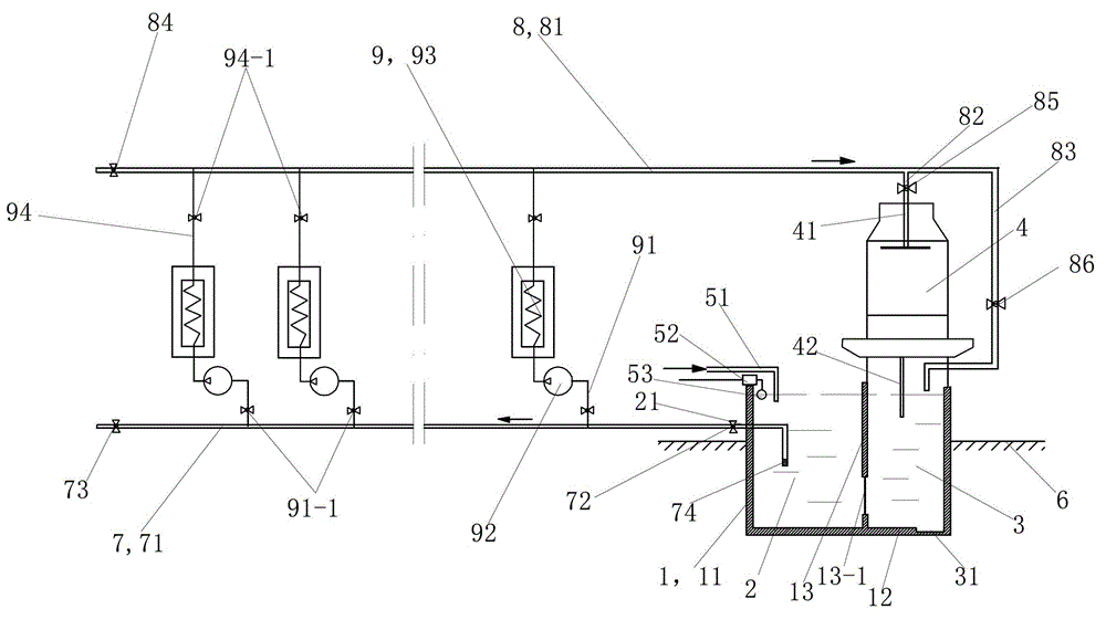
[0061] see figure 2 The rest of this embodiment is the same as in embodiment 1, except that: the return water pipeline 8 also includes a first discharge pipe 82, a second discharge pipe 83, a second backwater discharge gate valve 85 and a third backwater discharge gate valve 86. The proximal end of the return water main pipe 81 is connected to the water inlet of the first discharge pipe 82 and the water inlet of the second discharge pipe 83 through corresponding three-way joints. The first discharge pipe 82 is connected to the water inlet pipe 41 of the cooling tower 4 through a second backwater discharge gate valve 85. The water outlet of the second discharge pipe 83 is located above the backwater sedimentation tank 3, and the third backwater discharge gate valve 86 is connected in series on the second discharge pipe 83.
PUM
| Property | Measurement | Unit |
|---|---|---|
| Height | aaaaa | aaaaa |
| Depth | aaaaa | aaaaa |
Abstract
Description
Claims
Application Information
 - R&D
- Intellectual Property
- Life Sciences
- Materials
- Tech Scout
- Unparalleled Data Quality
- Higher Quality Content
- 60% Fewer Hallucinations
Browse by: Latest US Patents, China's latest patents, Technical Efficacy Thesaurus, Application Domain, Technology Topic, Popular Technical Reports.
© 2025 PatSnap. All rights reserved.Legal|Privacy policy|Modern Slavery Act Transparency Statement|Sitemap|About US| Contact US: help@patsnap.com


