System combined inverter
A technology of inverters and transformers, applied in the field of system combined inverters, can solve problems such as leakage current and high-frequency noise that cannot be completely avoided
- Summary
- Abstract
- Description
- Claims
- Application Information
AI Technical Summary
Problems solved by technology
Method used
Image
Examples
Embodiment 1
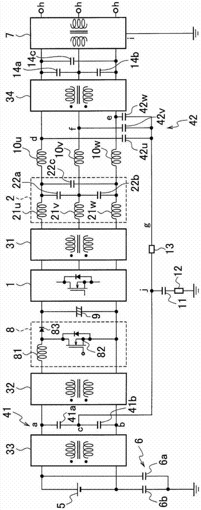
[0037] Such as figure 1 As shown, the grid-connected inverter of Embodiment 1 is a single-phase grid-connected inverter, and is configured as a solar power generation grid-connected inverter. In addition, in each of the following examples, with reference to figure 1 The structural elements of the system integrated inverter of the described embodiment 1 are the same as or equivalent to the structural elements, and are given the same as figure 1 Descriptions are made with the same symbols as those used in .
[0038] The system combined inverter of Embodiment 1 includes: an inverter 1, an output filter 2, a first common mode choke coil 31, a second common mode choke coil 32, a third common mode choke coil 33, a fourth common mode choke coil Common mode choke coil 34 , first capacitor pair 41 , second capacitor pair 42 , solar battery 5 , system transformer 7 , booster circuit 8 , DC linear capacitor (line condenser) 9 , normal mode (normal mode) reactor 10 , Grounded capacitor...
Embodiment 2
[0065] In the system joint inverter of embodiment 2, such as Figure 4 As shown, the first capacitor pair 41 of the system integrated inverter in Embodiment 1 is replaced with one first capacitor 41c, and the second capacitor pair 42 is replaced with one second capacitor 42c. From the connection point (point b) of the capacitor 41c and the output terminal on the negative side of the third common mode choke coil 33 (input terminal on the negative side of the second common mode choke coil 32) to the neutral point connection line g A capacitor 43a is inserted in the path up to point j above. A capacitor 43 b is inserted in the path from the connection point (point e) between the negative output terminal of the output filter 2 and the negative input terminal of the fourth common mode choke coil 34 to the second resistor 13 .
[0066]In the system combined inverter of Embodiment 1 above, the DC linear neutral point c formed on the input side of the inverter 1 and the AC output neu...
Embodiment 3
[0074] Such as Image 6 As shown, the grid-tie inverter of the third embodiment is configured such that the first reactor 21 ( 21 a , 21 b ) is removed from the output filter 2 of the grid-tie inverter of the first embodiment, and only the interphase capacitor 22 remains.
[0075] In the system combined inverter of Embodiment 1, the output filter 2 is composed of the first reactor 21 (21a, 21b) and the interphase capacitor 22, and the normal mode inductance component included in the first common mode choke coil 31 The same function as that of the first reactor 21 ( 21 a , 21 b ) of the output filter 2 is achieved. Therefore, in the grid-tie inverter of the third embodiment, the first reactor 21 ( 21 a , 21 b ) of the output filter 2 is replaced by the normal-mode inductance component of the first common-mode choke coil 31 .
[0076] According to the grid-tie inverter of Embodiment 3, like the grid-tie inverter of Embodiment 1 described above, leakage current and high-frequenc...
PUM
 Abstract
Description
Claims
Application Information
 - R&D
- Intellectual Property
- Life Sciences
- Materials
- Tech Scout
- Unparalleled Data Quality
- Higher Quality Content
- 60% Fewer Hallucinations
Browse by: Latest US Patents, China's latest patents, Technical Efficacy Thesaurus, Application Domain, Technology Topic, Popular Technical Reports.
© 2025 PatSnap. All rights reserved.Legal|Privacy policy|Modern Slavery Act Transparency Statement|Sitemap|About US| Contact US: help@patsnap.com


