
Device for controlling an adjustable drive element of an adjusting device and adjusting device

A driving element, control and adjustment technology, applied in the direction of movable seats, manual mechanisms, wing parts, etc., can solve problems such as wrong measurement

Inactive Publication Date: 2015-04-01
BROSE FAHRZEUGTEILE GMBH & CO KG
View PDF6 Cites 0 Cited by
  • Summary
  • Abstract
  • Description
  • Claims
  • Application Information

AI Technical Summary

Problems solved by technology

This leads to erroneous measurements when electronically measuring the position or movement of the drive element

Method used


Image

  • Device for controlling an adjustable drive element of an adjusting device and adjusting device
  • Device for controlling an adjustable drive element of an adjusting device and adjusting device
  • Device for controlling an adjustable drive element of an adjusting device and adjusting device

Examples


Embodiment Construction

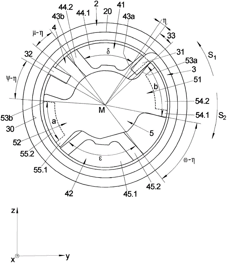
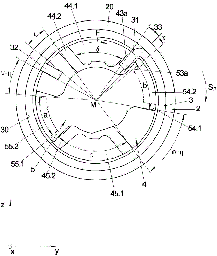
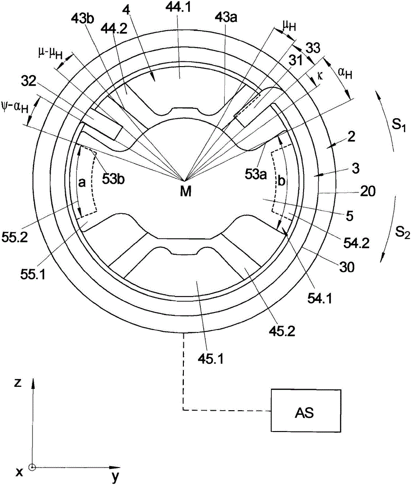
[0077] exist Figure 1A with 1B An embodiment of the adjusting device 1 according to the invention is illustrated in a cutaway side view. The main components of the adjusting device 1 are shown in the yz section plane. The double-acting adjusting device shown here with a load moment locking mechanism comprises a drive element 5 , an intermediate part 3 in the form of a coil spring and an output element 4 . Figure 1A with 1B The first and second contact claws 41 and 42 connected to or formed on the driven element in the sectional view of , protrude from the driven element. The drive element 5 , the intermediate part 3 and the driven element 4 are arranged in a common housing along the axis of rotation M consecutively or alongside one another.

[0078] The drive element 5 , the intermediate part 3 and the output element 4 are each mounted rotatably about an axis of rotation M within a common housing. In principle, however, it is possible for the respective axes of rotation f...


PUM


Abstract

The invention relates to a method for controlling an adjustable drive element of an adjusting device, wherein the drive element (5) drives an output element (4) by means of an intermediate part (3), the drive element (5), the intermediate part (3), and the output element (4) each are pivotally supported about a rotary axis (M), and wherein a drive side torque introduced by the drive element (5) is transmitted to the output element (4) by the intermediate part (3), while an output side torque introduced by the output element (4) is blocked by the intermediate part (3), having the following steps: Pivoting the drive element (5) in a first (S1; S2) of two potential and opposite adjusting directions (S1, S2) about the rotary axis (M) thereof, so that the drive element (5) acts in the first adjusting direction (S1; S2) on a section (31; 32) of the intermediate part (3) and a torque introduced into the intermediate part (3) by the drive element (5) via the segment (31; 32) of the intermediate part (3) is transmitted to the output element (4) to be driven, and stopping the drive element (5) when the output element (4) has reached an intended position (P2). According to the invention, the drive element (5) is pivoted into a neutral position in the second adjusting direction (S1; S2) opposite the first adjusting direction (S1; S2) by a prescribed distance (a) by the section (31; 32) of the intermediate part (3) by means of which the drive element (5) previously acted on the intermediate part (3), after the drive element (4) has reached the intended position (P2) thereof. The invention further relates to an adjusting device coupled to a controller implementing such a control method.

Description

technical field [0001] The invention relates to a method for controlling an adjustable drive element of an adjusting device and to an adjusting device. Background technique [0002] In such an adjusting device, the drive device drives the driven element via the intermediate part, wherein the drive element, the intermediate part and the driven element are each mounted rotatably about a rotational axis. An exemplary embodiment of such an adjusting device is an adjusting mechanism of a seat reclining device or of a window regulator, the middle part of which comprises a coil spring. In this case, the drive element, which is rotatable about its axis of rotation, is rotated so that it acts on the spring arms or legs of the coil spring, which is able to transmit the torque thus introduced into the coil spring. For the driven element which is also coupled with a coil spring. Usually, the drive element, the output element and the coil spring as an intermediate part are arranged in ...

Claims


Application Information

Patent Timeline
Patent Type & Authority Patents(China)
IPC IPC(8): B60N2/16B60N2/18B60N2/44E05F11/50E05F11/48B60N2/90
CPCE05Y2201/234B60N2/169E05F11/505B60N2/168E05Y2201/216B60N2/1889E05F11/488B60N2/444B60N2/938E05Y2900/55
Inventor 罗兰·卡尔布
Owner BROSE FAHRZEUGTEILE GMBH & CO KG
Learn More