
Differential leveling mechanism for hydrological flow measurement platform and leveling method

A leveling mechanism and differential technology, applied in the direction of supporting machines, mechanical equipment, machine platforms/supports, etc., can solve problems such as increased risk factors, affecting the accuracy of hydrological tests, hidden safety hazards, etc., and achieve low leveling power Effect

Active Publication Date: 2021-06-15
陈泉志
View PDF15 Cites 0 Cited by
  • Summary
  • Abstract
  • Description
  • Claims
  • Application Information

AI Technical Summary

Problems solved by technology

The inclination of the box not only affects the accuracy of the hydrological test, but also poses certain safety hazards
During the testing process of the hydrological flow measurement platform, the lifting operation will be carried out frequently. Due to the choice of the winding method of the suspension cable, the irregularity of the winding coil of the steel wire rope obtained by the shaft diameter of each winding makes it impossible to wind evenly, and then the hydrological flow measurement platform hangs. The inconsistency of the slings, when the span of the cableway is small, the inclination is small, which does not affect the test, but when the span is large, during the operation of the hanging box, due to the weight of the steel wire cableway itself and the hanging box, the cableway presents an arc During the operation of the hanging box, the whole hanging box is in a tilted state. In this tilted state, hydrological personnel are in a dangerous state when performing flow measurement operations, which increases the difficulty of the operation and greatly increases the risk factor.

Method used


Image

  • Differential leveling mechanism for hydrological flow measurement platform and leveling method
  • Differential leveling mechanism for hydrological flow measurement platform and leveling method

Examples


Embodiment 1

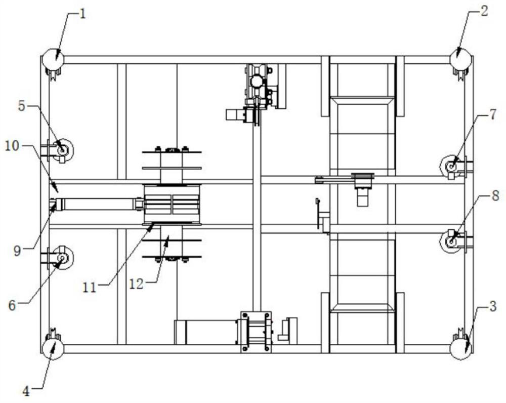
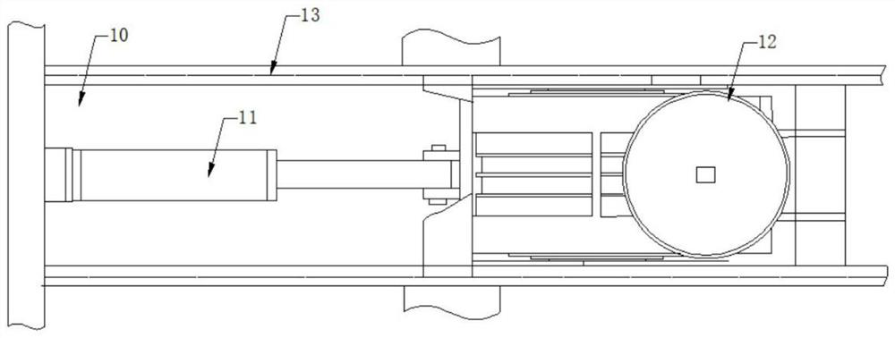
[0032] Such as Figure 1-2 As shown, the present invention provides a differential leveling mechanism for a hydrological flow measurement platform, including a platform frame, a sliding guide rail, a suspension cable, a leveling motor, a No. 1 guide wheel 1, an electric push rod 9, an ear plate 10, Push motor 11, reel 12, chute guide rail 13 and push motor 11, and the suspension cable changes from vertical to horizontal through No. 1 guide wheel 1, No. 2 guide wheel 2, No. 3 guide wheel 3 and No. 4 guide wheel 4 Direction, and through No. 5 guide wheel 5, No. 6 guide wheel 6, No. 7 guide wheel 7 and No. 8 guide wheel 8 respectively wound to the outside of reel 12, one end of electric push rod 9 is provided with push motor 11, pushes motor 11 It moves on the ear plate 10, the chute guide rails 13 are arranged on both sides of the ear plate 10, and the upper end of the push motor 11 is provided with a main motor seat.

[0033] Further, the push motor 11 is connected to the slid...


PUM


Abstract

The invention discloses a differential leveling mechanism for a hydrological flow measurement platform and a leveling method. The differential leveling mechanism is characterized in that a suspension cable is changed from a vertical direction to a horizontal direction through a first guide wheel, a second guide wheel, a third guide wheel and a fourth guide wheel, and is respectively wound to the outer side of a winding drum through a fifth guide wheel, a sixth guide wheel, a seventh guide wheel and an eighth guide wheel, a push motor is arranged at one end of an electric push rod, and sliding groove guide rails are arranged on the two sides of a lug plate. In the leveling process, one end of the left end and the right end of the platform rises, and the other end of the platform descends, so that the horizontal movement distance of the differential leveling winding drum is half of the height difference of the left side and the right side of the platform, the stroke amplification effect is achieved, and large-range leveling can be achieved through the electric push rod with the small stroke; and in the leveling process, the stress on the left side and the right side of the winding drum is basically balanced, so that the push rod only needs to overcome friction force and inertia force theoretically, the leveling power is very small, and an efficient and energy-saving leveling mode is achieved.

Description

technical field [0001] The invention relates to the technical field of hydrological equipment, in particular to a differential leveling mechanism and a leveling method for a hydrological flow measuring platform. Background technique [0002] There is a certain sag in the main cable during the cableway erection process, which causes a certain degree of inclination of the hydrological flow measurement platform originally in a horizontal state at a certain distance from the starting point. The inclination of the box not only affects the accuracy of the hydrological test, but also poses certain safety hazards. During the testing process of the hydrological flow measurement platform, the lifting operation will be carried out frequently. Due to the choice of the winding method of the suspension cable, the irregularity of the winding coil of the steel wire rope obtained by the shaft diameter of each winding makes it impossible to wind evenly, and then the hydrological flow measurem...

Claims


Application Information

Patent Timeline
Patent Type & Authority Applications(China)
IPC IPC(8): F16M11/04F16M11/18
CPCF16M11/043F16M11/18
Inventor 陈泉志陈艳薛小吉巩琳李玉珍
Owner 陈泉志
Learn More