
Color light-emitting diode (LED) lamp

A technology of LED lights and colored lights, applied in the field of LED colored lights, to achieve highly scientific effects

Inactive Publication Date: 2012-10-03
TIANJIN UNIV OF TECH & EDUCATION TEACHER DEV CENT OF CHINA VOCATIONAL TRAINING & GUIDANCE
View PDF0 Cites 2 Cited by
  • Summary
  • Abstract
  • Description
  • Claims
  • Application Information

AI Technical Summary

Problems solved by technology

Mainly used in home lighting environment and other places

Method used


Image

  • Color light-emitting diode (LED) lamp
  • Color light-emitting diode (LED) lamp
  • Color light-emitting diode (LED) lamp

Examples


Embodiment Construction

[0017] The following patents of the present invention are described in further detail through specific examples. The following patents of inventions are only descriptive, not limiting, and cannot limit the scope of protection of the patents of the present invention.

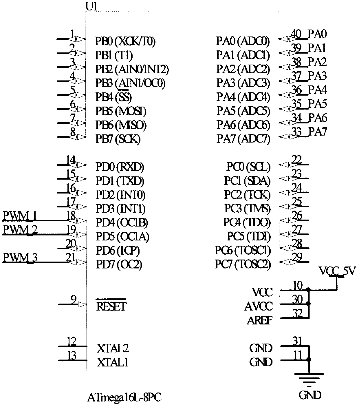
[0018] Such as figure 1 As shown, the novel LED colored lamp of the present invention is composed of MCU (1), LED lamp controller (2), LED lamp (3), and LED lamp drive circuit (4).

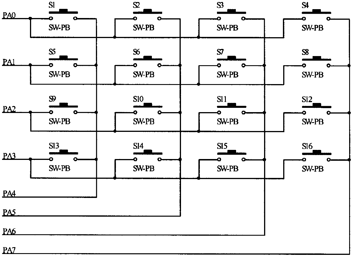
[0019] The LED light controller (2) sends a control signal to the MCU (1), and the MCU (1) controls the LED light driving circuit (4) to drive the LED light (3) to complete different lightings according to the control signal of the LED light controller (2). model.

[0020] Such as figure 2 As shown, the MCU (1) is composed of mega16 to complete the control signal acquisition and processing of the control circuit, and through the preset lighting scene, it can complete the lighting modes of various environments. Choose from differe...


PUM


Abstract

A color light-emitting diode (LED) lamp consists of a micro control unit (MCU) (1), an LED lamp controller (2), an LED lamp (3) and an LED lamp drive circuit (4). The LED lamp controller (2) sends a control signal to the MCU (1), and based on the control signal of the LED lamp controller (2), the MCU (1) controls the LED lamp drive circuit (4) to drive the turn-on or turn-off of the LED lamp (3). The color LED lamp is simple in structure, scientific and convenient, and can be applied to home lighting and the like.

Description

technical field [0001] The patent of the present invention relates to an LED colored light based on three primary colors, especially an LED colored light that can be dimmed and toned according to the needs of the scene. Background technique [0002] With the rapid development of the economy, people's requirements for the improvement of living standards are getting higher and higher. In daily life, people's requirements for lighting are also getting higher and higher. Lighting is not simply used for lighting. People often need higher requirements, especially higher requirements for light in different environments. In view of this, it is necessary to design a LED lantern based on three primary colors that can meet people's light requirements in different scenes and environments. Contents of the invention [0003] The purpose of this invention patent is to provide a special structure and control scheme for future LED lanterns to meet people's needs for light in different sce...

Claims


Application Information

Patent Timeline
Patent Type & Authority Applications(China)
IPC IPC(8): H05B37/02
Inventor 吴兴利田立国李春华陈志琦
Owner TIANJIN UNIV OF TECH & EDUCATION TEACHER DEV CENT OF CHINA VOCATIONAL TRAINING & GUIDANCE
Learn More