


Quick Research
Generate reliable direction feasibility study reports for your R&D in just a few steps.

Technical Q&A
Discover and master advanced knowledge NOW. Basics, ideas, possibilities, all at once.

Find Solutions
As an expert in R&D theories, this can generate solutions to your technical problems instantly.

Evaluate Feasibility
Analyze your overall solution with one click, know your potential R&D risks in advance.

Monitor Landscape
Get weekly tech updates, stay abreast of the latest tech innovations and key insights.
Tunnel establishment method, UE and NNI gateway
A technology for establishing tunnels and user equipment, applied in electrical components, transmission systems, etc., can solve the problem that the scene with a large number of tunnels is not suitable, and achieve the effect of smooth capacity expansion
- Summary
- Abstract
- Description
- Claims
- Application Information
AI Technical Summary
Problems solved by technology
Method used
Image

Examples
Embodiment 1
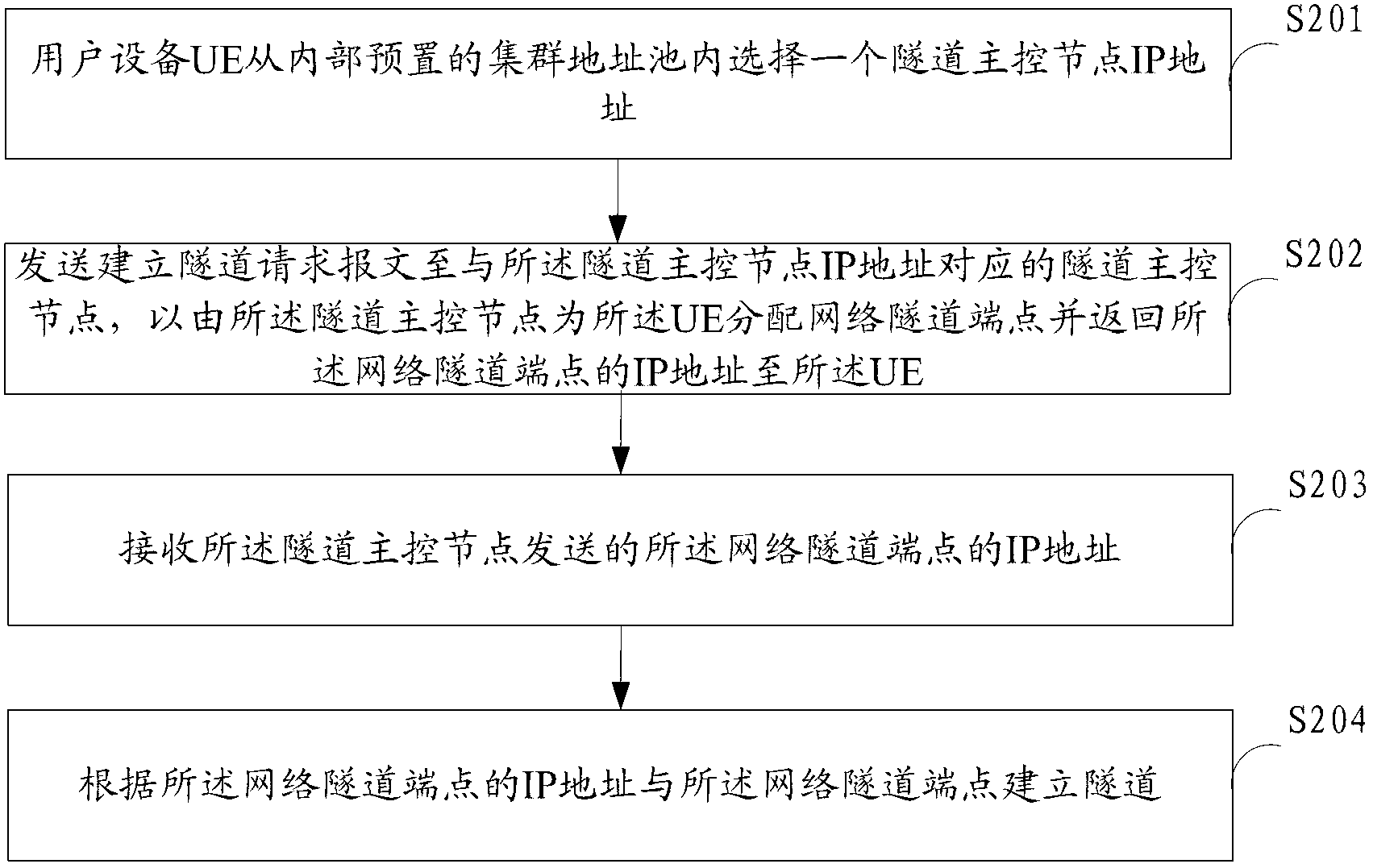
[0046] figure 2 The implementation process of the method for establishing a tunnel provided by Embodiment 1 of the present invention is shown, and the user equipment side is taken as an example to illustrate, and the details are as follows:
[0047] In step S201, the user equipment UE selects an IP address of a tunnel master control node from an internal preset cluster address pool.
[0048] Since the UE does not know which port of the NNI interface gateway is idle when sending a tunnel establishment request message, and a port can contain multiple network tunnel endpoints, so if there are many UEs, the NNI interface gateway cannot accurately select the network Tunnel endpoint (Network Tunnel Endpoint, NTE).
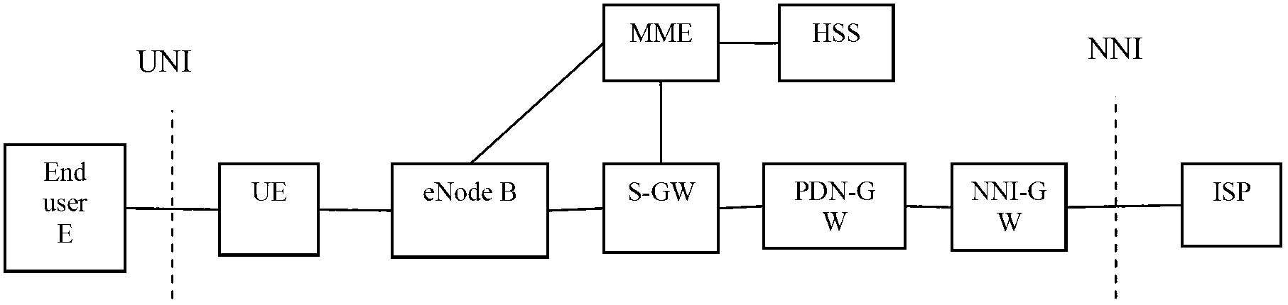
[0049] In this embodiment, the tunnel master control node TMN is responsible for selecting the network tunnel endpoint NTE according to the service flow and configuration principles, wherein the tunnel master control node TMN is located on the NNI interface gateway, an...
Embodiment 2
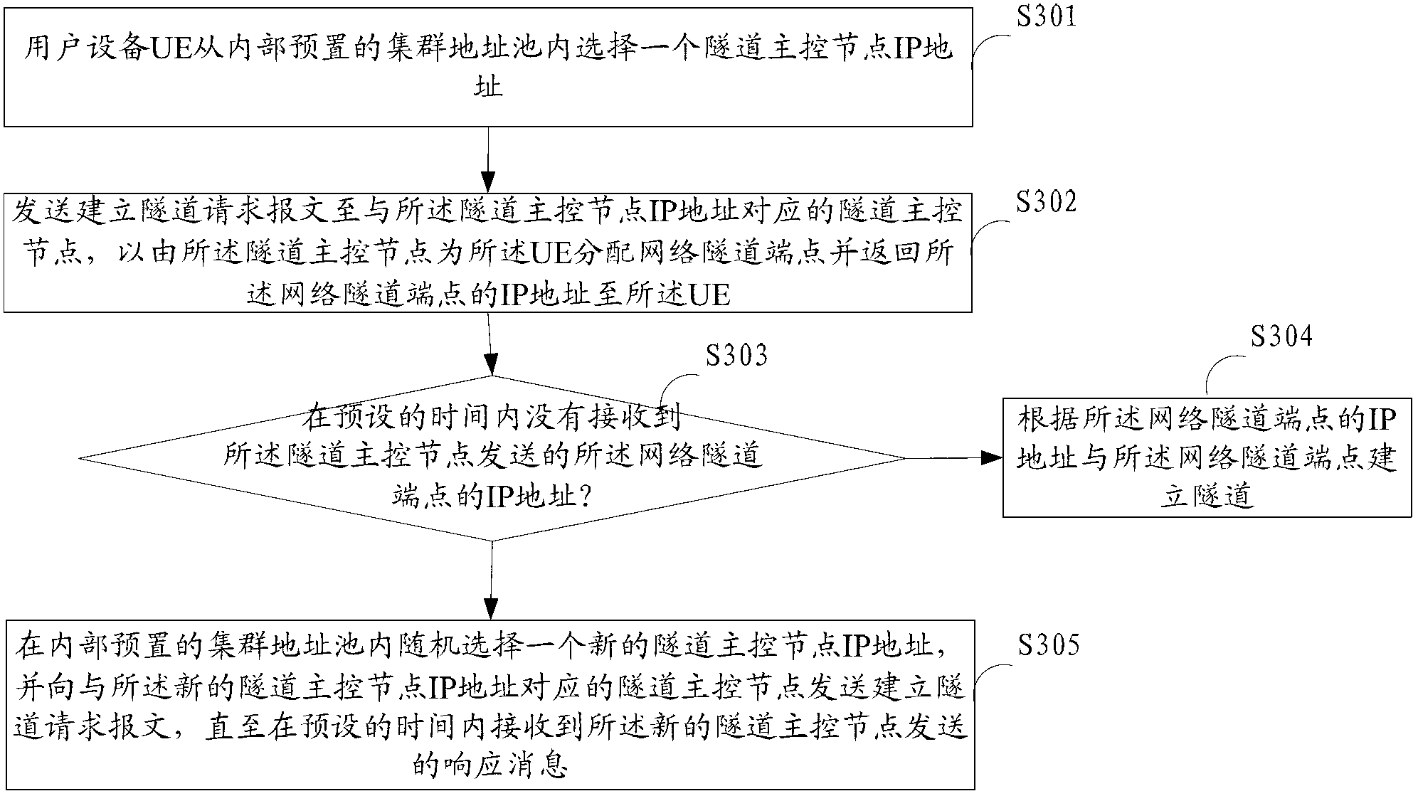
[0060] image 3 The implementation process of the method for establishing a tunnel provided by Embodiment 2 of the present invention is shown, and the user equipment side is taken as an example for illustration, and the details are as follows:
[0061] In step S301, the user equipment UE selects an IP address of a tunnel master control node from an internal preset cluster address pool.
[0062] In step S302, send a tunnel establishment request message to the tunnel master control node corresponding to the IP address of the tunnel master control node, so that the tunnel master control node allocates a network tunnel endpoint for the UE and returns the network tunnel IP address of the endpoint to the UE.
[0063] In step S303, if the IP address of the network tunnel endpoint sent by the tunnel master control node is not received within the preset time, then step S304 is executed; otherwise, step S305 is executed.
[0064] In this embodiment, the UE detects whether the IP addre...
Embodiment 3
[0071] Figure 4 The implementation process of the method for establishing a tunnel provided by Embodiment 3 of the present invention is shown, and the side of the tunnel master control node is taken as an example for illustration, and the details are as follows:
[0072] In step S401, a tunnel establishment request message sent by a user equipment UE is received.
[0073] In step S402, a network tunnel endpoint is allocated to the UE.
[0074] In this embodiment, the tunnel master control node allocates network tunnel endpoints to the UE according to locally stored service flows of all network tunnel endpoints and preset configuration principles.
[0075] Specifically, the network element list configured inside the tunnel master control node stores the working status information of all network tunnel endpoints NTE, and the working status information includes port quantity, port number, flow information, failure or not, priority and so on. The master control node needs to kn...
PUM
 Abstract
Description
Claims
Application Information
 - R&D Engineer
- R&D Manager
- IP Professional
- Industry Leading Data Capabilities
- Powerful AI technology
- Patent DNA Extraction
Browse by: Latest US Patents, China's latest patents, Technical Efficacy Thesaurus, Application Domain, Technology Topic, Popular Technical Reports.
© 2024 PatSnap. All rights reserved.Legal|Privacy policy|Modern Slavery Act Transparency Statement|Sitemap|About US| Contact US: help@patsnap.com