
An Improved DC Bus Voltage Control Method for Two-Stage Converter

A technology of DC bus voltage and control method, which is applied in the direction of converting AC power input to DC power output, electrical components, single-network parallel feeding arrangement, etc., and can solve the problem of DC bus voltage impact, increased fluctuation, and deterioration of system dynamic performance, etc. question

Active Publication Date: 2014-10-15
苏州钧灏电力有限公司
View PDF1 Cites 0 Cited by
  • Summary
  • Abstract
  • Description
  • Claims
  • Application Information

AI Technical Summary

Problems solved by technology

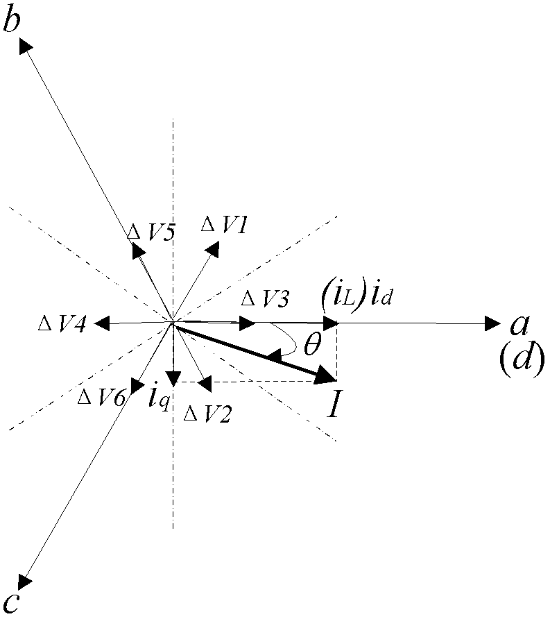
The dead zone effect of the DC / AC inverter causes the voltage error vector to be related to the inverter output current. In practical applications such as supercapacitor energy storage systems, frequent charging and discharging lead to frequent switching of the output power direction of the DC / AC side, resulting in voltage The error vector changes, which affects the dynamic performance of the current loop. In severe cases, the dynamic performance of the system will be deteriorated, and the impact and fluctuation of the DC bus voltage of the system will increase.

Method used


Image

  • An Improved DC Bus Voltage Control Method for Two-Stage Converter
  • An Improved DC Bus Voltage Control Method for Two-Stage Converter
  • An Improved DC Bus Voltage Control Method for Two-Stage Converter

Examples


Embodiment Construction

[0018] The technical solution of the present invention will be further described in detail according to the accompanying drawings in the description.

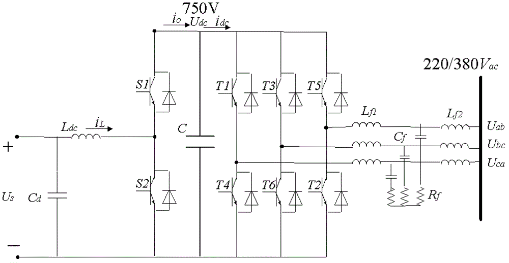
[0019] The main circuit structure of the two-stage converter is as follows: figure 1 As shown, it includes the front-stage DC / DC power conversion unit and the rear-stage DC / AC power conversion unit, and finally connects to the grid or load through the LCL filter. The DC / DC module adopts independent PWM control mode: when the lower bridge arm performs PWM modulation and the upper bridge arm is turned off, the circuit is in the Boost discharge state; when the upper bridge arm performs PWM modulation and the lower bridge arm is turned off, the circuit is in the Buck charging state ; The DC / AC module uses space vector modulation (SVPWM).

[0020] The relationship between the voltage error vector caused by the dead zone effect on the DC / AC side and the inverter output current is as follows: figure 2 shown. Assuming that the angl...


PUM


Abstract

The invention belongs to the technical field of control of converters in distributed generation and energy supply microgrid systems and relates to an improved method for controlling direct current (DC) bus voltage of a two-stage converter. The method has the following beneficial effects: on the basis of two-closed-loop control of the conventional DC bus voltage outer loop and the inverter output current inner loop, two auxiliary control methods, namely inverter dead-time compensation and dynamic power feedforward, are added, wherein the impacts of the error voltage vector caused by the dead-time effect on the dynamic performances of the current inner ring can be effectively eliminated through the inverter dead-time compensation; and the dynamic power feedforward is a first derivative element and can ensure the current reference of the current inner loop to track power output of the preceding DC / DC module in real time; and by adopting the two auxiliary control methods, DC bus voltage surge and fluctuation in the transient state of the two-stage converter can be effectively suppressed and the dynamic responses of the two-stage converter can be improved.

Description

technical field [0001] The invention belongs to the technical field of converter control of distributed power generation and energy supply micro-grid systems, and in particular relates to an improved two-stage converter DC bus voltage control method. Background technique [0002] With the increasing consumption of fossil fuels such as traditional coal and oil, distributed power generation technology using clean or renewable energy is increasingly widely used in power supply systems. Distributed power sources, such as photovoltaic power generation, wind power generation, micro gas turbines, and lithium battery energy storage, all output direct current or high-frequency alternating current. Therefore, in order to meet power supply needs, converters such as DC / DC or DC / AC are usually used as distributed power sources An energy conversion interface device connected to the power grid. Since the inverter needs a higher DC voltage when it is working normally (without a step-up tra...

Claims


Application Information

Patent Timeline
Patent Type & Authority Patents(China)
IPC IPC(8): H02J3/38H02M7/5387
Inventor 王成山李霞林郭力
Owner 苏州钧灏电力有限公司
Learn More