Dynamic centrifuge integrated rigid arm

A technology of centrifuges and rotating arms, which is applied in the direction of centrifuges, can solve the problems of limited dynamic acceleration range of centrifuges, large driving power of centrifuges, and huge structure of centrifuges, so as to ensure uniformity and consistency of mechanical properties, and ensure Stability and safety, the effect of increasing stability and safety

Active Publication Date: 2017-09-19
GENERAL ENG RES INST CHINA ACAD OF ENG PHYSICS
View PDF6 Cites 0 Cited by
  • Summary
  • Abstract
  • Description
  • Claims
  • Application Information

AI Technical Summary

Problems solved by technology

Using this method to produce variable acceleration has the following three disadvantages: one is that the direction of acceleration borne by the tested product is constantly changing due to the rotation of the small turntable; the other is that the acceleration borne by the tested product is a synthetic acceleration, which is difficult to accurately Third, under a certain acceleration, the range of dynamic acceleration produced by the centrifuge is limited, and the dynamic acceleration produced by the centrifuge is mainly realized by changing the acceleration radius of the test piece
The reason why the traditional dynamic centrifuge adopts the double turntable structure is mainly because the professional technicians have calculated and analyzed that the dynamic function of the centrifuge can be directly realized by the rotating arm structure. Due to the large moment of inertia of the rotating arm body, the driving power of the centrifuge will be reduced. It is very large, and the structure of the centrifuge is also very large, which is almost impossible to realize, so instead of directly using the integrated arm, a double turntable structure is adopted

Method used


Image

  • Dynamic centrifuge integrated rigid arm
  • Dynamic centrifuge integrated rigid arm
  • Dynamic centrifuge integrated rigid arm

Examples


Embodiment Construction

[0028] The present invention will be further described below in conjunction with accompanying drawing:

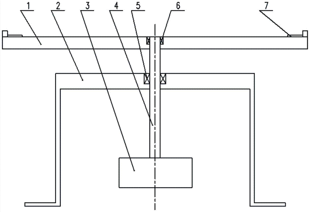
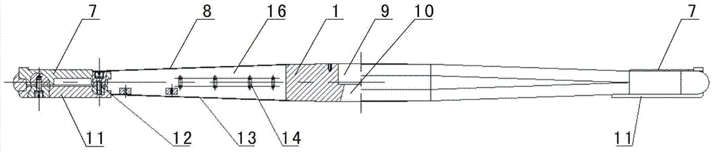
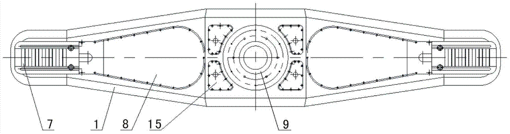
[0029] Such as Figure 2-Figure 7 As shown, the integrated rigid rotating arm of the dynamic centrifuge of the present invention includes a rotating arm body 1, and a vertical mounting hole is provided at the center of the rotating arm body 1, and the mounting hole includes an upper cylindrical expansion sleeve coupling hole 9 and the central positioning hole 10 of the upper, lower, and large conical shapes located at the bottom, the pivoting arm body 1 is a steel body with an integrated structure, and the pivoting arm body 1 is a shuttle-shaped shape with a large middle and small left and right ends, and The arm body 1 is a symmetrical structure with front and back symmetry, left and right symmetry, and up and down symmetry, and the front and rear sides of the arm body 1 are convex arc-shaped; On the sample stage 7 where the test piece is installed, a "T" shaped mounting ...


PUM


Abstract

The invention discloses an integrated rigid rotating arm of a dynamic centrifuge. The shape of the shuttle is large in the middle and small at the left and right ends, and the main body of the rotating arm is a symmetrical structure with front and rear symmetry, left and right symmetry, and up and down symmetry. Sample stages for installing test pieces are respectively installed above the ends of the rotary arm body, and counterweights for one-to-one correspondence with the sample stages are respectively installed under the left and right ends of the rotary arm body to realize left-right symmetry of the rotary arm body. The rigid rotary arm of the present invention has stronger rigidity, lower moment of inertia and smaller air damping, which ensures that the centrifuge has high dynamic performance, and the variable acceleration is directly generated through the variable speed movement of the rotary arm body, which solves the problem of Traditional dynamic centrifuge acceleration needs synthesis, direction change and other issues.

Description

technical field [0001] The invention relates to a rotating arm of a dynamic centrifuge, in particular to an integrated rigid rotating arm of a dynamic centrifuge. Background technique [0002] A dynamic centrifuge is a test device that utilizes rotation to generate changing acceleration (or jerk rate) to assess the acceleration adaptability of products. The dynamic performance of the centrifuge, that is, the ability of the centrifuge to produce the rate of acceleration change is the core index of the centrifuge. In order to improve the dynamic performance of the centrifuge, it is theoretically hoped that the moment of inertia of the rotating part of the centrifuge should be as small as possible. [0003] At present, the common experimental centrifuge is the constant acceleration centrifuge, which uses the steady-state acceleration generated after the centrifuge is running to evaluate the product. [0004] Due to its special purpose, the dynamic centrifuge is less studied at...

Claims


Application Information

Patent Timeline
Patent Type & Authority Patents(China)
IPC IPC(8): B04B7/00
Inventor 王军黎启胜王小龙刘静刘伟王彩霞陈练吴付岗
Owner GENERAL ENG RES INST CHINA ACAD OF ENG PHYSICS
Why Eureka
Try Eureka