
Modular power supply device with reverse prevention function and reverse-prevention control circuit

A technology of control circuit and power supply device, which is applied in the direction of output power conversion device, emergency protection circuit device, control/regulation system, etc., and can solve problems such as uneven flow of diodes, lower module efficiency, and increased module radiator. Achieve the effect of improving module load adjustment rate, improving module efficiency, and simple and reliable structure

Inactive Publication Date: 2012-10-03
BEIJING DINGHAN TECH GRP CO LTD
View PDF4 Cites 11 Cited by
  • Summary
  • Abstract
  • Description
  • Claims
  • Application Information

AI Technical Summary

Problems solved by technology

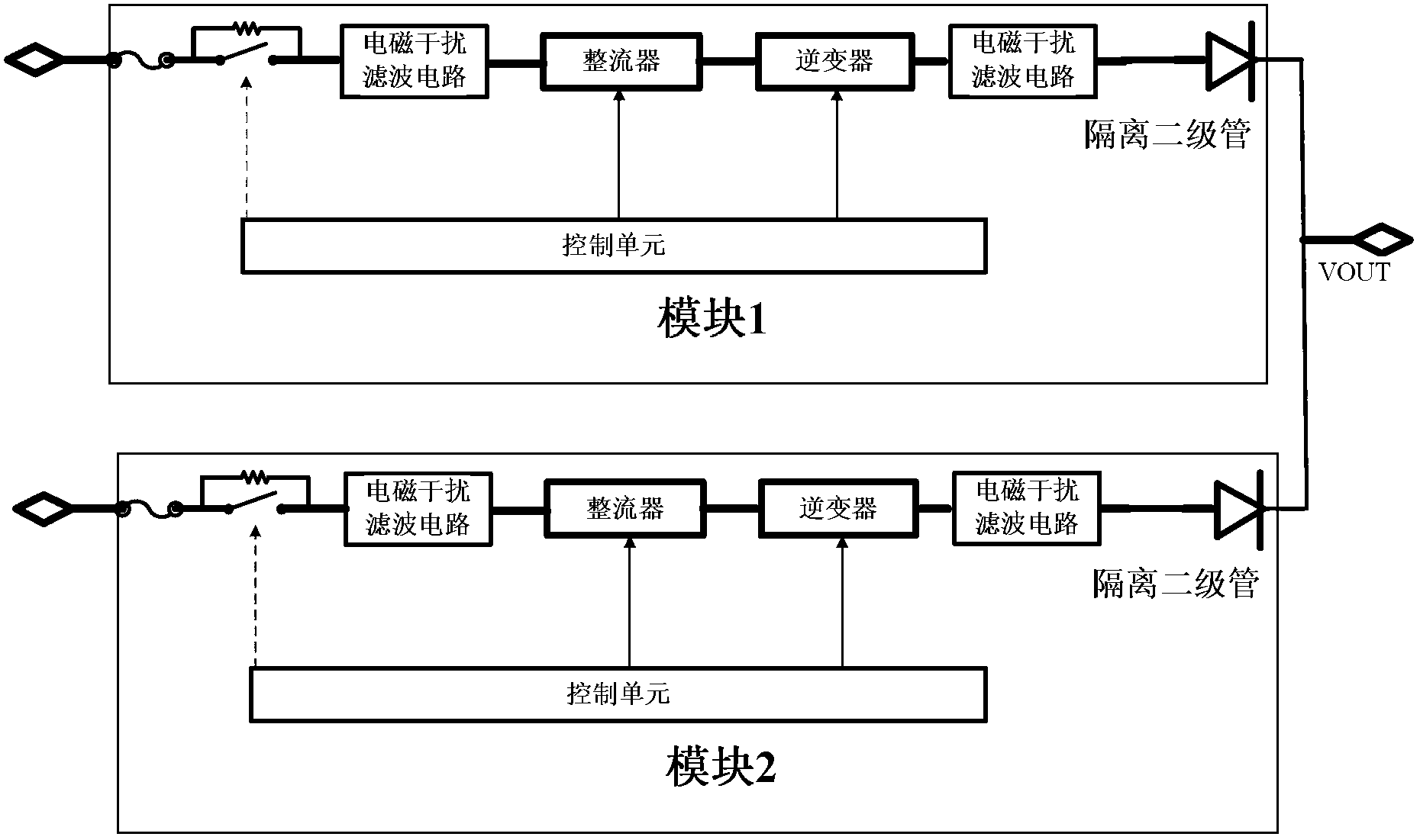
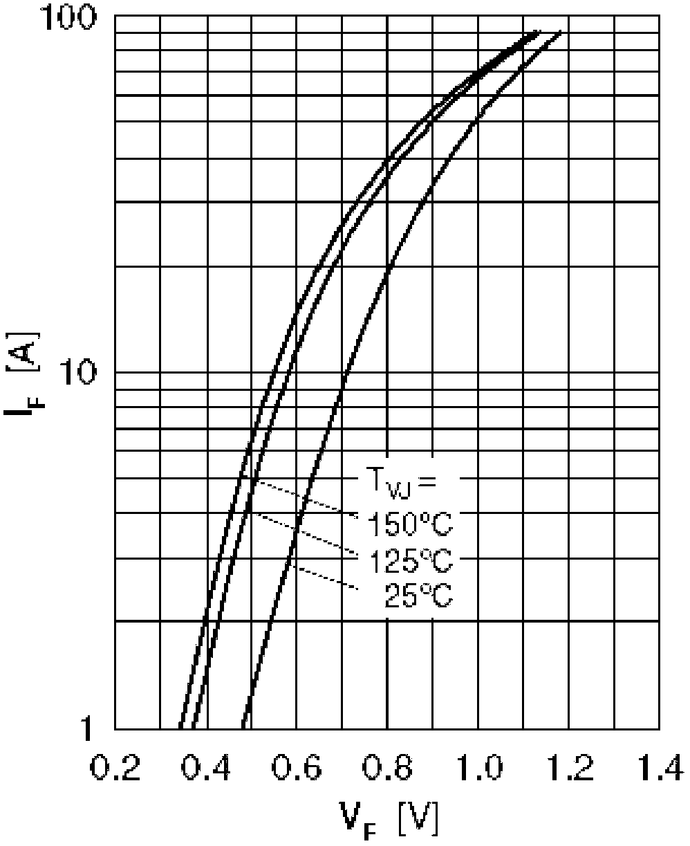
This technical solution has the advantages of simple and reliable circuit structure and less components used, and is suitable for module power supplies that output small current power supplies, but in practical applications, there are the following disadvantages: 1) The high loss caused by the forward conduction voltage drop of the isolation diode, The efficiency of the module is reduced, and at the same time, the high loss brings serious thermal problems, which leads to the increase of the module radiator and the increase of the module volume; 2) The forward conduction voltage drop of the isolation diode is proportional to the load current, resulting in poor load regulation of the module ;3) The isolation diode is self-isolated and uncontrolled, and the reverse recovery will cause a reverse transient current, which will cause the output signal to oscillate; 4) When multiple diodes are connected in parallel, the diode with a negative temperature coefficient will produce serious uneven current, and the load concentrated on individual diodes, causing the diodes to overheat and damage
The above shortcomings are more prominent in low-voltage and high-current signal power modules

Method used


Image

  • Modular power supply device with reverse prevention function and reverse-prevention control circuit
  • Modular power supply device with reverse prevention function and reverse-prevention control circuit
  • Modular power supply device with reverse prevention function and reverse-prevention control circuit

Examples


Embodiment Construction

[0032] The present invention will be further described below in conjunction with drawings and embodiments. The present invention is described by taking a standardized railway signal module power supply as an example. For example, the standardized railway signal module power output specification is a voltage of 24V, a rated current of 75A, and a peak current of 82.5A. Combined with the above main parameters of the power supply of the railway signal module, it will be described in detail through specific embodiments.

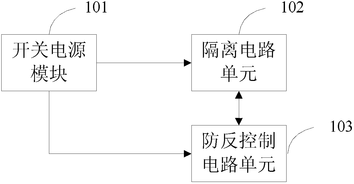
[0033] image 3 A functional block diagram of a modular power supply device with an anti-reverse function provided for a specific embodiment of the present invention. Such as image 3 As shown, the modular power supply device with anti-reverse function includes a switching power supply module 301, an isolation circuit unit 302 and an anti-reverse control circuit unit 303, and the switching power supply module 301 and the isolation circuit unit 302 and the anti-...


PUM


Abstract

The invention discloses a modular power supply device with a reverse prevention function and a reverse-prevention control circuit. An isolation circuit and a reverse-prevention control circuit are additionally arranged on an output end of the traditional switching mode power supply module, and the reverse-prevention control circuit is used for controlling the work state of the isolation circuit so as to further make the output of the switching mode power supply module controllable. By means of the technical scheme, the circuit is simple and reliable in structure, the oscillation-free smooth switching of the switching mode power supply module can be realized, the modular efficiency is increased, and the modular load regulation rate is increased.

Description

technical field [0001] The invention relates to the field of switching power supplies, in particular to a modularized power supply device with an anti-reverse function and an anti-reverse control circuit. Background technique [0002] With the intelligentization, informatization and networking of the railway transportation command system, the application scope of railway signal power supply is gradually developing towards the comprehensive centralized power supply system. At present, railway signal power supplies use standardized power modules to supply power to railway equipment. The power supply of the railway signal module adopts two-way power supply-main-standby input. After automatic switching by the AC contactor, it is filtered by electromagnetic interference, boosted and rectified by a high-frequency rectifier with parallel current sharing, and converted by high-frequency (DC / DC) to All kinds of DC power output, module power supply parallel current sharing output to ...

Claims


Application Information

Patent Timeline
IPC IPC(8): H02M3/156H02H7/10
Inventor 汤益锋魏学业马治国
Owner BEIJING DINGHAN TECH GRP CO LTD
Learn More