Variable excitation brushless alternating-current generator

An alternator, electrical connection technology, applied in electrical components, electromechanical devices, electric components, etc., can solve problems such as poor low-speed charging performance, and achieve the effects of improved charging performance, good charging performance, and high magnetic field strength

Inactive Publication Date: 2012-10-03
李慧杰
View PDF4 Cites 1 Cited by
  • Summary
  • Abstract
  • Description
  • Claims
  • Application Information

AI Technical Summary

Problems solved by technology

Although the brushless alternator does not have the disadvantages of the brushless alternator, the excitation winding of the brushless alternator does not rotate with the generator rotor, and two additional gaps are added in the magnetic circuit, which makes the biggest disadvantage of the brushless alternator The low-speed charging performance is poor. Another disadvantage of the brushless alternator is that the working speed of the best charging performance is between 4000r / min-8000r / min, and 8000r / min is only allowed to work for half an hour at most, because the current passing through the excitation winding is slightly The magnetic field generated by large is slightly stronger, and its working speed should not be higher than 10000r / min under any circumstances, so the application of brushless alternators in automobiles is not as widespread as that of brushed alternators.

Method used


Image

  • Variable excitation brushless alternating-current generator
  • Variable excitation brushless alternating-current generator
  • Variable excitation brushless alternating-current generator

Examples


Embodiment Construction

[0011] The present invention will be further described below in conjunction with the accompanying drawings and embodiments.

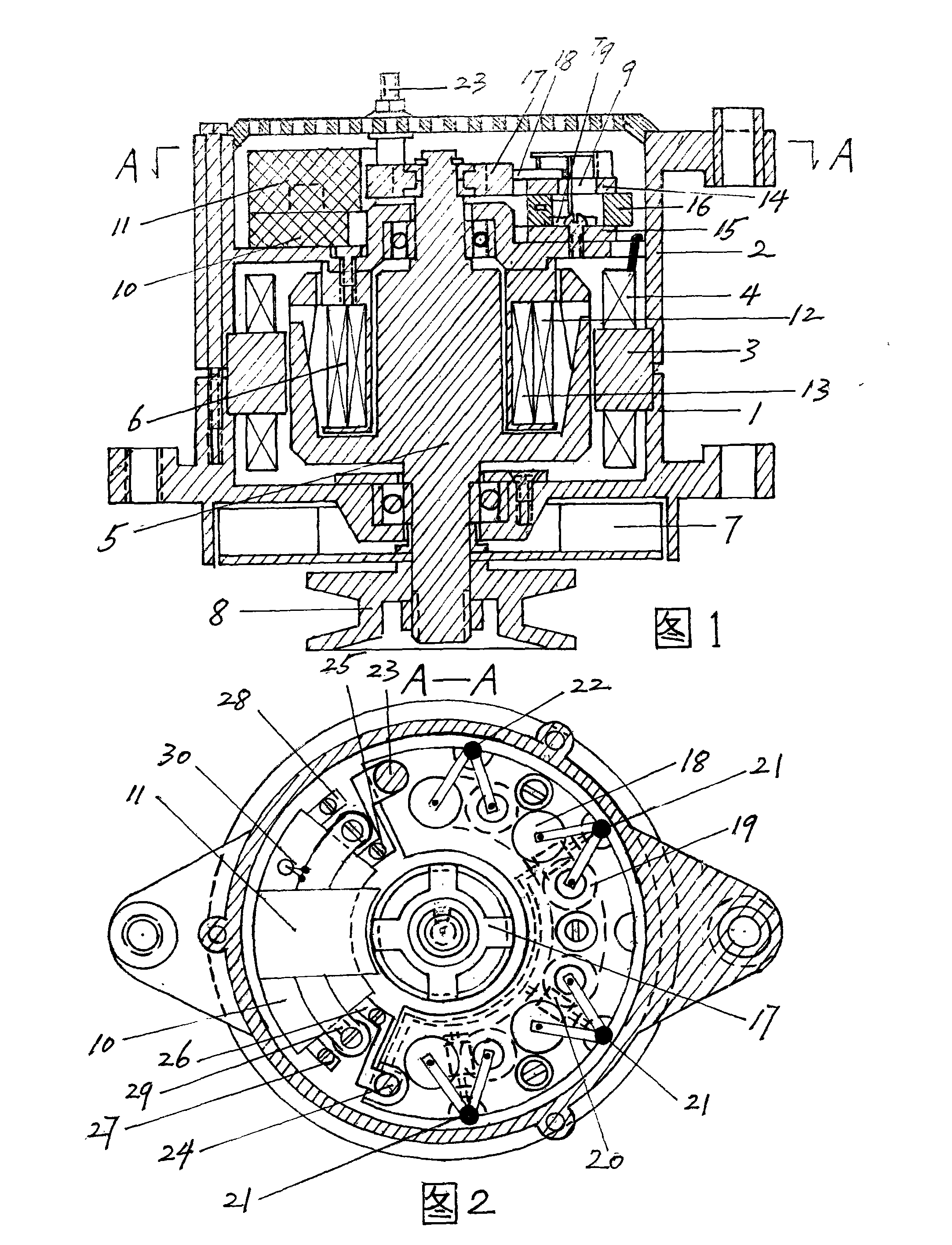
[0012] exist figure 1 The shown variable excitation brushless alternator is mainly composed of a front end cover 1, a rear end cover 2, a stator assembly composed of a stator assembly core 3 and a stator three-phase winding 4, a rotor assembly composed of a rotor 5 and a double excitation winding 6 Cheng, fan 7, belt pulley disc 8, rectifier 9, transformer and voltage regulator 10, electromagnetic generator speed sensor 11. The stator assembly consisting of the iron core 3 of the stator assembly and the stator three-phase winding 4 covers the front end cover 1 with the front end cover 1 and the rear end cover 2 with bolts, and is composed of the rotor 5 and the double excitation winding 6 The rotor assembly is assembled in the front end cover 1 and the rear end cover 2 and the inner ring of the iron core 3 of the stator assembly. The front end of the r...


PUM


Abstract

The invention discloses a variable excitation brushless alternating-current generator which has the advantages of good charging performance in low speed operation, middle speed operation and high speed operation and being free from frequent maintenance. The generator is characterized by consisting of a rotor assembly assembled in an inner ring of a stator assembly between a front end cover and a rear end cover, a rectifier fixed at the rear end of the rear end cover, a variable excitation and voltage adjustor, and a speed sensor of the generator, wherein three leads of the head end of stator three-phase winding of the stator assembly and one lead of the middle point of the stator three-phase winding of the stator assembly are electrically connected with four groups of rectifier diodes of the rectifier respectively; the variable excitation and voltage adjustor is electrically connected a lead at the head end of the rotor assembly double-excitation winding and two leads at the tail end of the rotor assembly double-excitation winding, an output of the rectifier and exciting pins through pins respectively, wherein the rotor assembly is fixed on the rear end cover; and the leads are electrically connected with the speed sensor of the generator.

Description

Technical field: [0001] The invention belongs to the technical field of generator production for automobile power supply equipment, and in particular relates to a variable-stimulation brushless alternator. Background technique: [0002] At present, there are two types of alternators used in automobiles, one is a brushed alternator, and the other is a brushless alternator. Both alternators are mainly composed of a front cover, a stator assembly, a rotor Assembly, rear end cover, rectifier, voltage regulator, fan and pulley disc, etc. Stator assembly consists of stator core and stator three-phase winding; rotor assembly consists of rotor and excitation winding; rectifier consists of positive element board, negative element board, four rectifying positive diodes, four rectifying negative diodes, three exciting diodes It is composed of an insulating post plate, four rectifying positive diodes are installed on the positive element board, and the negative poles are electrically c...

Claims


Application Information

Patent Timeline
Patent Type & Authority Applications(China)
IPC IPC(8): H02K29/14H02K3/28H02K11/00H02K11/21
Inventor 李慧杰
Owner 李慧杰
Why Eureka
Try Eureka