
Device for eliminating joint seam of rear projector splicing wall

A rear-projection splicing wall splicing and splicing wall technology, applied in the direction of identification devices, instruments, etc., can solve the problems of destroying the overall display effect of the image, splitting the displayed image, etc., achieving good image display continuity, improved display effect, and easy installation. Effect

Inactive Publication Date: 2012-10-03
GUANGDONG VTRON TECH CO LTD
View PDF17 Cites 21 Cited by
  • Summary
  • Abstract
  • Description
  • Claims
  • Application Information

AI Technical Summary

Problems solved by technology

The advantage of the splicing screen is that it can improve the resolution of the system display and increase the display area. It can not only display a complete picture on the entire display screen, but also open windows at any position on the display screen. However, the connection between each display unit There is a seam at the place, and the width of the seam is generally less than 1mm. When the display is actually started, it is visually reflected as a black border, and the displayed image has a feeling of being split, which destroys the overall display effect of the image.

Method used


Image

  • Device for eliminating joint seam of rear projector splicing wall
  • Device for eliminating joint seam of rear projector splicing wall
  • Device for eliminating joint seam of rear projector splicing wall

Examples


Embodiment Construction

[0026] The technical solutions of the present invention will be further described below in conjunction with the accompanying drawings and embodiments.

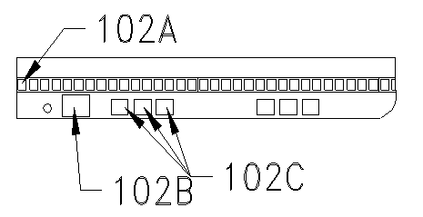
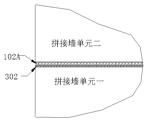
[0027] like figure 1 As shown, it is a schematic diagram of the structure of the present invention; a device for eliminating the joints of the rear projection mosaic wall. LED light 102A, LED light display control device 102 and fixing device 103 are arranged at the place, wherein, LED light 102A is installed at the seam 100 recessed on the surface of the video wall unit, that is, the LED light 102A and the surface of the video wall unit 101 are not on the same plane Above: the fixing device 103 is installed on the frame 104 of the mosaic wall unit, the LED lamp 102A and the LED lamp display control device 102 are fixed at the joint 100 through the fixing device 103, and the LED lamp 102A is connected to the LED lamp display control device 102.

[0028] The fixing device 103 is a fixing plate, which can be made of a metal pla...


PUM


Abstract

The invention relates to the field of a large-screen display device, in particular to a device for eliminating a joint seam of a rear projector splicing wall. The rear projector splicing wall comprises a plurality of splicing wall units, wherein a joint seam is respectively formed between every two adjacent splicing wall units, the joint seam is provided with a light emitting diode (LED) lamp and an LED lamp display control device, and the LED lamp is connected with the LED lamp display control device. The joint seam of the rear projector splicing wall is provided with the LED lamp, so that the light transmitted from the LED lamp passes through the joint seam to be displayed, the problem of the black edge of the joint seam of the rear projector splicing wall can be effectively solved, the all-day display effect of the splicing wall can be greatly improved, and the display effect is remarkable; and moreover, the LED lamp display control device reads pixels on the edges of the splicing wall units, and the pixels on the edges read are displayed by controlling the LED lamp, so that the image display continuity is good, and the phenomenon that the image is split suddenly can be avoided.

Description

technical field [0001] The invention relates to the field of large-screen display devices, in particular to a device for eliminating seams in rear projection splicing walls. Background technique [0002] With the improvement of people's demand for display information transmission, the application fields of large-screen display have spread to various fields such as public display, transportation dispatching and commanding, weather monitoring, power and telecommunications monitoring, fire monitoring and commanding, and military commanding. [0003] The existing rear-projection video wall large-screen display technology mainly combines and displays multiple video wall units by stacking. The advantage of the splicing screen is that it can improve the resolution of the system display and increase the display area. It can not only display a complete picture on the entire display screen, but also open windows at any position on the display screen. However, the connection between ea...

Claims


Application Information

Patent Timeline
Patent Type & Authority Applications(China)
IPC IPC(8): G09F9/33
Inventor 刘志文钟杰婷
Owner GUANGDONG VTRON TECH CO LTD
Learn More