
Vibrating disk type drier with burbling function

A vibrating plate and dryer technology, applied in the direction of dryers, drying chambers/containers, drying, etc., can solve the problems that the seamless cooperation between the scraper and the heating plate surface cannot be guaranteed, the purity of the material is reduced, and it is not very smooth.

Inactive Publication Date: 2012-10-03
SHENYANG INSTITUTE OF CHEMICAL TECHNOLOGY
View PDF6 Cites 6 Cited by
  • Summary
  • Abstract
  • Description
  • Claims
  • Application Information

AI Technical Summary

Problems solved by technology

However, it cannot be used for drying powdery and granular materials that require high purity and strong abrasiveness. Due to the relationship between the equipment structure and working principle, the heating plate is mostly welded, and the surface is not very smooth. Even if it is machined to ensure a certain flatness, After the heating medium is passed into the heating plate, it will also be deformed, and the rotation of the vertical shaft and the production of the scraper cannot guarantee the seamless cooperation between the scraper and the heating plate. Because the dry material particles are fine and hard, it is equivalent to the surface of the plate and the scraper. The friction caused by the abrasive is increased between the plates, and as the operation time increases, the material of the heating plate or the scraper in contact with the material will be lost and mixed into the material, resulting in a decrease in the purity of the material after drying

Method used


Image

  • Vibrating disk type drier with burbling function
  • Vibrating disk type drier with burbling function
  • Vibrating disk type drier with burbling function

Examples


Embodiment Construction

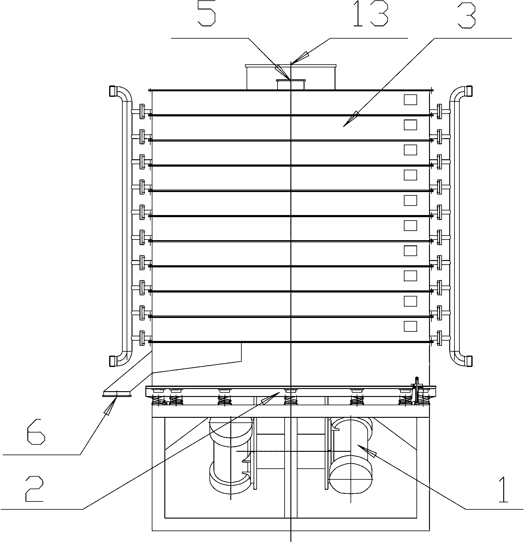
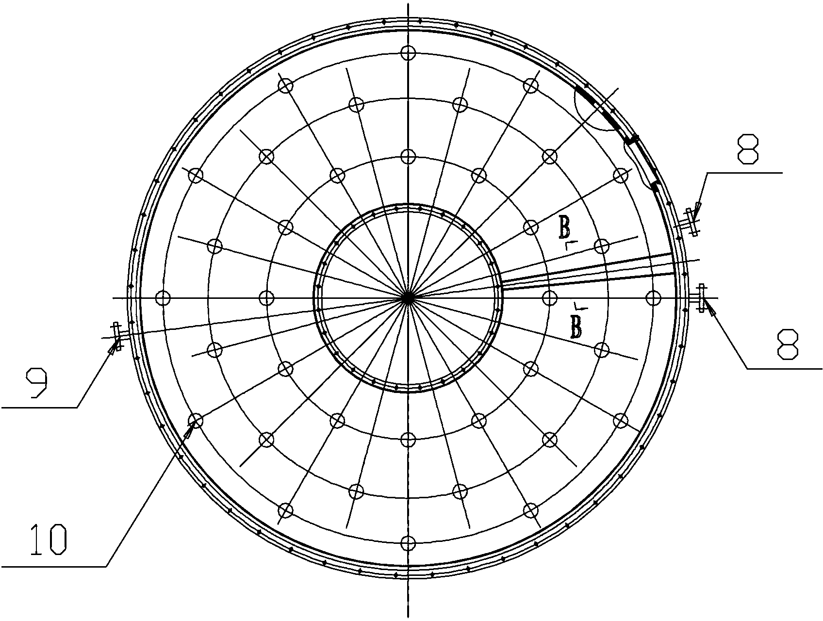
[0015] Such as Figure 1 to Figure 3 As shown, a vibrating disc dryer with turbulence function includes a vibrating motor 1, a vibrating chassis 2 and a vibrating spring arranged therebetween. It is characterized in that: above the vibrating chassis 2, several The vibrating plate 3, the upper and lower surfaces of each vibrating plate 3 are respectively provided with an inlet and an outlet, and the outlet of each vibrating plate 3 corresponds to the entrance position of the vibrating plate 3 below; the upper surface of the uppermost vibrating plate 3 is for feeding Port 5, the outlet of the lower surface of the bottom vibrating plate 3 is the discharge port 6; an interlayer 7 is provided at the bottom of each vibrating plate 3, and the interlayer 7 and the oil inlet 8 arranged on the outer circumference of the vibrating plate 3 It communicates with the oil outlet 9, the oil inlet 8 of each layer of vibrating plate 3 communicates with the oil inlet pipe, and the oil outlet 9 of...


PUM


Abstract

The invention relates to a vibrating disk type drier with a burbling function. The vibrating disk type drier comprises a vibration motor, a vibration chassis and a vibration spring arranged between the vibration motor and the vibration chassis, wherein vibrating disks are arranged above the vibration chassis, the upper and lower surfaces of each vibration chassis are respectively provided with an inlet and an outlet; the bottom of each vibrating disk is provided with an interlayer, and the interlayers are communicated with oil inlets and oil outlets formed in the outer periphery of the vibrating disks; and the inner periphery of each interlayer is provided with a plurality of peripheries which are at equal intervals, each periphery is provided with a plurality of burbling pillars which are uniformly distributed, and the burbling pillars of the adjacent two peripheries are distributed in an overlapping manner. The drier adopts a receiving broken vibration mode to ensure that a material can do horizontal circle operation, the conjugation generated friction in mechanical movement is avoided, and high-purity and high-hardness particle material can be continuously dried; and meanwhile, the power consumption is small so that the energy-saving purpose can be realized as no machine driving member exists, and a burbling structure does a disturbing action on the flow of heating a medium in the vibrating disks so that the heat transmission is enhanced.

Description

technical field [0001] The invention relates to a vibrating disc dryer with flow-disturbing function, which is suitable for continuous drying of powdery and granular materials with low bulk density, easy to fly, high purity requirements or strict requirements on heating temperature. Background technique [0002] At present, for the continuous drying of some powdery materials with small bulk density and easy to fly, or heat-sensitive materials that require high temperature changes, disc-type conduction heat exchange dryers are mostly used. The traditional tray dryer is to add materials to the first layer of heating plate from the upper part. The dryer is composed of multi-layer heating plates from top to bottom and a vertical shaft in the middle. The diameters of the heating plates are different. The upper part is equipped with scrapers of different shapes. Under the action of the scraper rotating the vertical shaft, the first layer of material falls on the second layer of he...

Claims


Application Information

Patent Timeline
Patent Type & Authority Applications(China)
IPC IPC(8): F26B17/00F26B23/10F26B25/18
Inventor 王学平张振伟
Owner SHENYANG INSTITUTE OF CHEMICAL TECHNOLOGY
Learn More